docs.unavlab.com
Main ❯ Navigation & tracking systems ❯ RedWAVE User’s manual
| www.unavlab.com support@unavlab.com |
RedWAVE - underwater acoustic navigation system User’s manual |
RedWAVE
User’s manual
Contents
- 1. Introduction
- 2. System composition
- 3. Effective deployment of a long navigation base
- 4. Possible malfunctions, their diagnosis and elimination
- 5. Liability and disclaimer
1. Introduction
Underwater acoustic navigation system RedWAVE is designed to provide navigation data (absolute geographic coordinates and depth) of various underwater objects in a submerged state:
- remote-controlled unmanned underwater vehicles (ROV);
- manned underwater vehicles;
- autonomous unmanned underwater vehicles (AUV);
- recreational divers, technical divers (when using a diver’s version of the system).
The principle of operation of the RedWAVE system is similar to the principle of operation of global satellite navigation systems such as GPS, GLONASS and the like. The main difference is that small floating buoys RedBASE - repeaters of satellite navigation signal act as navigation satellites.
Geographic coordinates are generated directly on the navigation receiver, which is an acoustically passive device. This architecture of the system allows to simultaneously provide navigation data to an unlimited number of navigation receivers with the use of one set of four buoys in one water area.
RedWAVE uses state-of-the-art digital broadband acoustic communication technology, and the applied signal is specially Designed for difficult hydrological conditions, including conditions characteristic of shallow water bodies.
2. System composition
2.1. RedBASE - GNSS-equipped sonobuoy
Regardless of the positioned objects - divers or robots, the RedWAVE system necessarily includes four navigation buoys RedBASE.
2.1.1. General information
GNSS-equipped sonobuoys RedBASE are designed to build a long navigation base in water bodies for supporting diving navigation receivers RedNAV and/or navigation receivers for robots RedNODE.
A long navigation base is formed by four buoys RedBASE. Each buoy set contains four buoys with numbers (addresses) from “1” to “4”, the number in the set determines the isolating code channel of communication. Therefore, for the operation of the system requires the presence of all buoys of the set.
It is possible to replace buoys with buoys from another set with the same addresses, any other options are unacceptable and will lead to the inability to determine coordinates using navigation receivers.
A general view of the buoy is presented in figure 1.
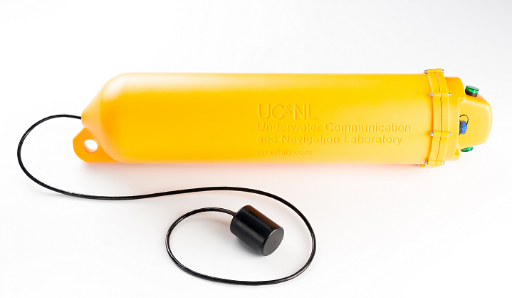 |
| Figure 1 - GNSS-equipped sonobuoy RedBASE |
Buoys are to located in the water area on the water surface, their position is fixed using anchors.
ATTENTION! It is worth remembering that although the buoys have a small positive buoyancy, they are not intended for direct mounting on anchor rope. To unload the buoy from the weight of the anchor rope, additional floats corresponding to the weight of the rope should be used.
Figure 2 1 shows the recommended deployment scheme for a buoy in a water body.
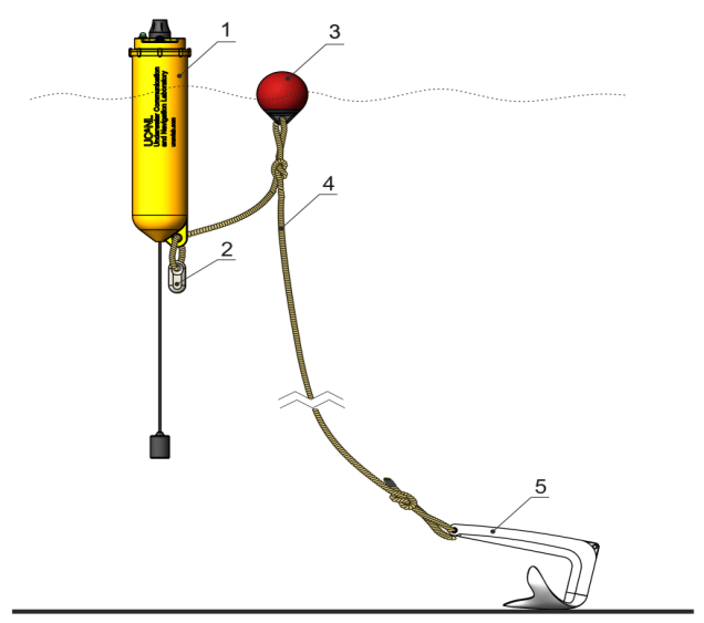 |
| Figure 2 - RedBASE recommended deployment scheme |
| 1 - GNSS-equipped sonobuoy RedBASE, 2 - additional weight2, 3 - float, 4 - anchor rope, 5 - anchor |
1Images may vary slightly from supplied products.
as the manufacturer is constantly working to improve the performance and make design changes.
2 Additional weight is used only in underloaded version.
Figure 3 shows the location of the controls and indicators on the buoy cover.
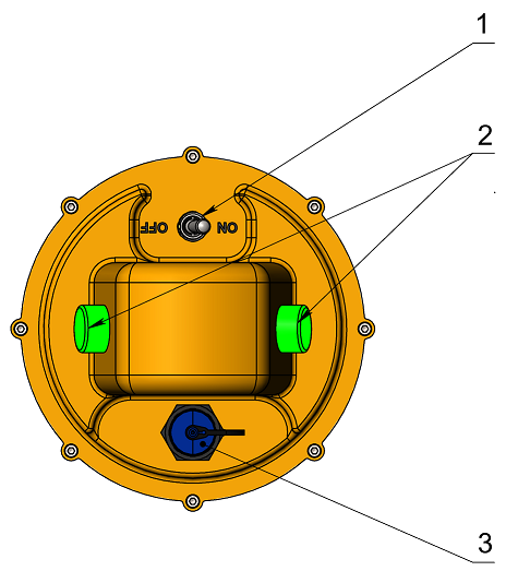 |
| Figure 3 - Controls and indicators on the cover of RedBASE |
| 1 - power toggle switch, 2 - indicator lights, 3 - charging connector |
2.1.2. Operating modes and light indication
The buoys in each set have different numbers (addresses) from 1 to 4. When a buoy is turned on using the toggle switch 4 (see Figure 3), the buoy through indicator 2 reports its number in the set: the number of flashes corresponds to the number of the buoy.
If the buoy is equipped with a light mast, the flashes will be duplicated on it.
After blinking its number, the buoy turns into operating mode. If the buoy’s battery is charged, the indicator will light constantly, until the built-in GPS/GLONASS receiver detects signals from satellites of the global satellite navigation system. After which it will flash 1 time in 4 seconds. The number of flashes in this case also corresponds to the number of buoys in the set.
If the buoy’s battery is in a state where less than 20% of the charge remains, the indicator will flash 1 time per second. The number of flashes in this case also corresponds to the number of buoys in the set.
ATTENTION! If the user noticed flashes 1 time per second, the buoy should be turned off as soon as possible and put on charge. Long-term operation with a discharged power source is not allowed.
If the battery is in a critical discharge state, then after blinking with its number, the buoy will automatically turn off, in which case the indicator will also turn off. The buoy must be charged immediately to avoid failure of the internal power source.
2.1.3. Preparation for use
Before installing the buoy directly, make sure:
- in the integrity of the rubber cap of the toggle switch 1 (see Figure 3);
- that the cover of the charging connector 3 (see Figure 3) is tightly screwed;
- the light indication is OK and the built-in power source of the buoy is not discharged (see 2.1.2.)
ATTENTION! Almost all known cases of buoy failure are related to the fact that the user uses a buoy with an opened cover of charging connector! Do not use buoys with an opened connector cover and may result in water entering the device. Failure of buoys due to water entering through an open charging connector is non-warranty!
2.1.4. Storage and maintenance
No special storage and maintenance requirements are imposed on buoys, with the exception of the following:
- When used in seawater and/or heavily polluted water, desalination is necessary (sediment and flushing in freshwater);
- The use of any organic solvents, strong acids, alkalis and other aggressive substances is not allowed;
- If necessary, washing in household soap solutions is possible;
- The impact of shock or significant static loads is not allowed, both on the buoy body and on the controls: toggle switch, light indicator lamps, charging connector, etc.;
- During long-term storage (more than 1 month), it is necessary to recharge the devices to prevent degradation of the built-in battery;
- The use of third-party chargers is not allowed;
- Strong (with a radius of less than 5 cm) bending of the cable of the hydroacoustic transmitter is not allowed;
- Do not store upside down, hanging on a load-carrying eye, etc .;
The chargers supplied with the buoys may vary slightly from kit to kit (in terms of indicating the status and completion of the charging process), so carefully read the attached instructions carefully before using them.
2.2. RedNODE - navigation receiver
2.2.1. General information
It is easiest to understand its purpose and the functionality of the integrated navigation receiver RedNODE, starting from the analogy with ordinary GNSS receivers: when connected to a vessel, the receiver receives hydroacoustic signals from four buoys RedBASE and determines its own geographical position, and the built-in temperature and pressure sensor allows the vessel to additionally determine the depth, thereby providing the user with information about the position in three-dimensional space. Coordinates are generated in the receiver itself and are accessible via the serial interface according to the NMEA0183-like protocol. In this regard, if transmission of the coordinates calculated by the receiver to the control panel is required, this should be done through the vessel’s information channel.
2.2.2. Interfacing and placement requirements
The receiver should be installed in a position in which line of sight with transmitters of all four buoys will be ensured (see paragraph 3). It should be located as far as possible from outputs of propulsors and various noisy mechanisms, sonars, etc. And also from units and modules that give strong electromagnetic interference (switching power supplies, motors, etc.).
When physically pairing the device with the vessel, it is necessary to ensure a reliable and tight cable entry that prevents water from flowing through the free end of cable. When sealing the free end of the cable, aggressive sealants and compounds (for example, silicone sealant based on acetic acid, etc.) should not be used, since its components can cause corrosion of the cable cores and lead to failure of the device.
It is not recommended to use compositions based on epoxy resins for sealing cable glands, as the latter, firstly, often collapse and lose their properties under prolonged exposure to moisture, and secondly, they give significant shrinkage after the cure.
The most reliable and suitable are compounds and sealants based on polyurethanes. In case of any questions about sealing, it is recommended to consult with the manufacturer.
Power requirements are specified in device specification. For information on information exchange with the device and changes in its configuration, refer to the description of the pairing protocol.
2.3. RedNAV - Diver’s navigation receiver
Diver’s navigation receiver RedNAV designed to provide navigation data to divers and accordingly, it is necessary only in the case of diving operations.
2.3.1. General information
The diver’s navigation receiver RedNAV allows a diver to determine the geographic location when submerged without the need for ascent and the use of floating GPS antennas on the cable. Working with the device RedNAV is in many ways similar to working with GPS/GLONASS trackers and navigators, with the only difference being that small-sized floating buoy transponders of a satellite navigation system signal play the role of positioning system satellites. For the operation of an unlimited number of devices RedNAV in one water area, 4 floating relay buoys RedBASE are required. The unique functionality and ease of use make RedNAV an ideal solution for recreational diving, as well as for search, archaeological and other underwater operations. The general view of the device is shown in Figure 4.
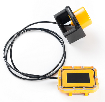 |
| Figure 4 - diver’s navigation receiver RedNAV |
| General view |
The interface unit contains the following main controls and modules:
- a screen for displaying navigation and service information;
- two piezo buttons on the sides, to control the device;
- built-in battery;
- Bluetooth module;
- DSP unit;
- wireless charge receiver.
The acoustic navigation receiver is connected to the interface unit using a cable and can be installed:
- on the shoulder of a diver;
- on a special panel that the diver holds in his hands;
- on the tank to ensure the minimum possible acoustic shading.
Optimum operating conditions for the acoustic receiver are achieved when there is a line of sight between the navigation receiver and the acoustic transmitters of all four buoys RedBASE throughout the entire time of use. This position is discussed in more detail in par. 3.3..
2.3.2. Work with the device, modes and user interface
2.3.2.1. Navigation mode
To turn on the device user must simultaneously press both buttons of the device located on the side surfaces of the interface unit.
ATTENTION! The diver’s navigation receiver is equipped with piezo buttons to exclude the possibility of device failure due to water entering the housing through mechanical button seals. Piezo buttons have some operational features, in particular, the lack of feedback when pressed. Buttons perceive only a short change in pressure, therefore, all presses in order to control the device should be short.
After switching on, the device, not installed on the charging pad, automatically switches to navigation mode. The appearance of the device screen in navigation mode immediately after switching on is shown in Figure 5.
ATTENTION! Immediately after switching on, the device calibrates atmospheric pressure for 10 seconds to more accurately determine the depth. Therefore, turning on the device is recommended only in the air. If at startup the hydrostatic pressure exceeds 1100 mbar, then atmospheric pressure calibration is not performed, and the standard value 1013.25 mbar is taken as atmospheric pressure.
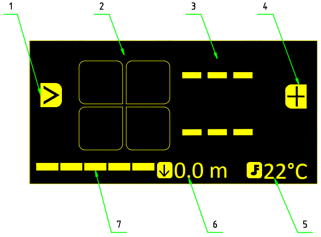 |
| Figure 5 - Main screen in navigation mode |
| After start up |
| 1 - Left button function (target switch), 2 - buoys status, 3 - azimuth and distance to target, 4 - right button function (mark current position), 5 - water temperature, 6 - depth (distance to the water surface), 7 - battery charge |
When buoy signals are not received (for example, immediately after switching on), the azimuth and distance to the target are not displayed on the screen, because the geographic location of the navigation receiver is either unknown or obviously out of date. Button functions are also not available in this case. Figure 6 illustrates the situation when the navigation receiver received a signal from the first buoy, but its own location has not yet been determined. It is worth remembering that the transmission of buoy signals is time-divided, and the receiver awaits their signals sequentially. Accordingly, if the reception of the 1st buoy does not occur, then the reception of the 2nd is not conducted, etc.
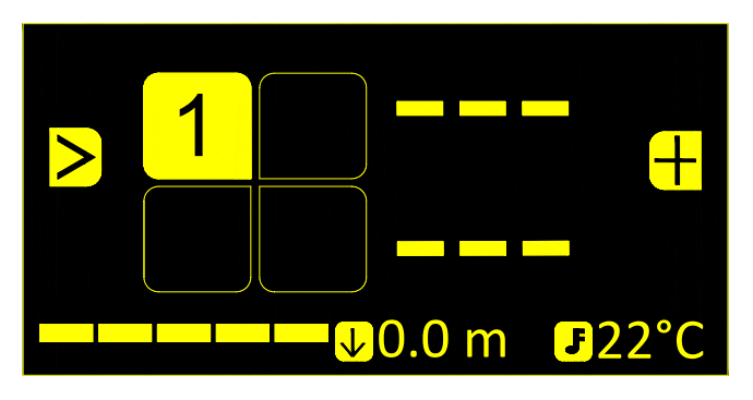 |
| Figure 6 - The main screen of the device during operation |
| Device has received signal from Buoy No. 1. Own location has not been determined yet |
When signals from all buoys are received and the coordinates of the navigation receiver are updated, the main screen has the form, as in Figure 7. For example, buoys with numbers 2 and 4 have a low charge of the built-in power supply, therefore, they are displayed as open squares with colour inversion. Buoy No. 1 is selected as the navigation target and its icon is displayed enlarged.
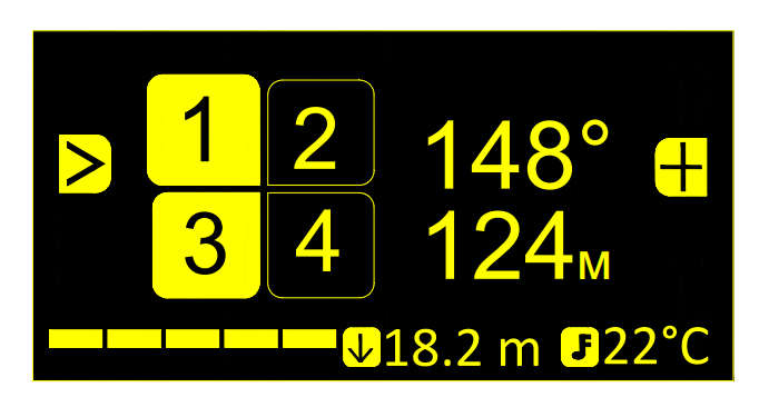 |
| Figure 7 - The main screen of the device during operation |
| Location determined. The buoy No. 1 was chosen as the navigation target |
In the 3 field (see Figure 5) Azimuth and distance to the target Azimuth and distance to the selected buoy are displayed. By azimuth here we mean the angular direction from the northern half-meridian clockwise to the line to the target.
ATTENTION! When approaching the target at a distance of fewer than 3 meters, instead of the angular direction to the target, dashes ”- - -“ are displayed.
When the location is determined (azimuth and distance to the selected target are displayed), when the user presses the left button (>), the next target in the list is selected (after Buoy No. 1, 2, 3 and 4). If waypoints have been preloaded into the device, they are located in the target list after the buoys. When switching navigation targets, the corresponding navigation information (Azimuth and distance) also changes.
When the user presses the right button (+), the current location is saved separately (the marked point is saved), which is placed at the end of the target list. An informational message is displayed, as in Figure 8.
 |
| Figure 8 - Message confirming that the current location has been saved |
The preloaded and marked points are numbered, and when the user selects them as targets using the (>) button, they are displayed as in Figure 9.
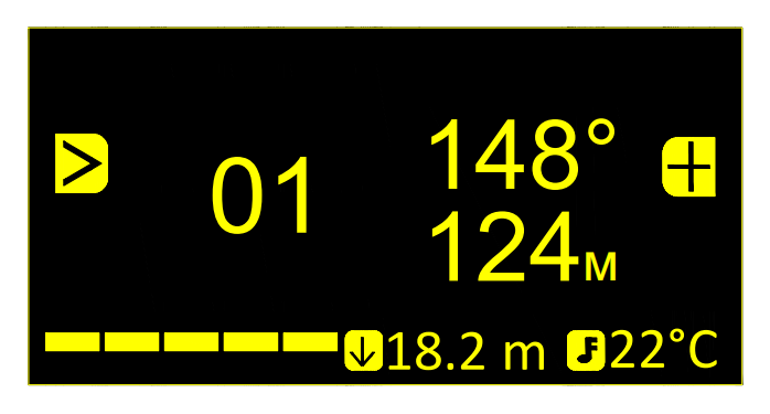 |
| Figure 9 - The main screen of the device during operation |
| The first waypoint/marked point is selected as a navigation target |
To turn off the device, the user must simultaneously press both buttons. In this case, the device will ask for confirmation of shutdown, as shown in Figure 10.
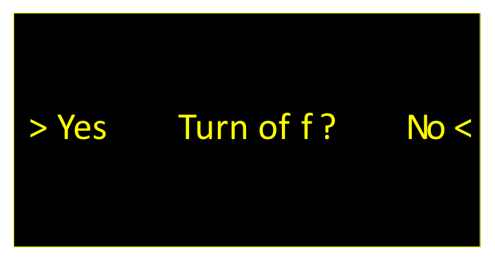 |
| Figure 10 - Shutdown confirmation |
2.3.2.2. Service mode
When the interface unit is installed on the charging pad, it switches into service mode. In this mode, the built-in power supply is charged and the device configuration is possible. Figures 11 and 12 show the device screen after installation on the charging pad. The state of charge and wireless connection are displayed by the brightness of the corresponding icons.
It should be remembered that the charging platform must contact directly with the housing of the interface unit. If a belt is attached to the interface unit, it should be pulled back and a charging pad placed between the interface unit housing and the belt. Otherwise, the distance between the transmitter of the charger and the receiver inside the housing of the interface unit will be too far to provide the required charging current.
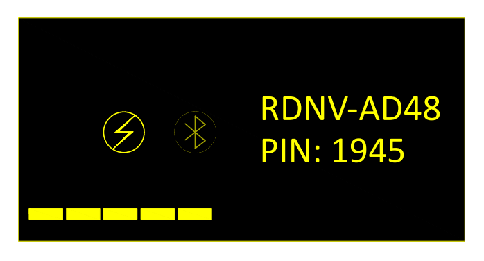 |
| Figure 11 - Screen view of the device in service mode |
| The charging icon lights up brightly - the charge is on, the Bluetooth icon is darkened - the connection is not established |
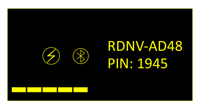 |
| Figure 12 - Screen view of the device in service mode |
| Both icons glow brightly - the charge is on, a Bluetooth connection is established |
When the device is on the charging platform, after 5 minutes inactivity, the screen turns off in order to save energy and charge the built-in power supply faster. Pressing any button on the interface device again turns on the screen.
When the interface unit is removed from the charging pad, the device automatically turns off.
2.3.2.3. Built-in Bluetooth module and PC connection
The diver’s navigation receiver contains a Bluetooth module for:
- device configuration using a PC;
- transfer of coordinates to an external system in real-time (Bluetooth GNSS-receiver emulation).
The module turns on when the device starts, regardless of the mode in which it is on and off after 10 minutes to save power if no connection has been established to it during this time.
The module of each navigation receiver has a unique name for the Bluetooth device, having the format:
RDNV-XXXX
where XXXX is a unique identifier consisting of uppercase letters and numbers. An example of how the Bluetooth name of the device is displayed is shown in Figures 11 and 12 (RDNV-AD48). Below, under the line with the name of the device, a hint is displayed containing a pin code (in this example, pin code 1945), which must be entered when the device is initially connected to an external system.
If a Bluetooth connection occurs when the device is in navigation mode, it transmits navigation information, in particular messages GGA, RMC and MTW.
Thus, the diver’s navigation receiver RedNAV can act as a Bluetooth GNSS-receiver, the data from which can be used to display the location of the diver in real-time on any mapping device, for example, on a diver’s tablet that supports connecting an external GNSS-receiver via Bluetooth. It is worth remembering that radio waves practically do not penetrate the water column, and for stable operation of the Bluetooth connection underwater, devices (the interface unit of the diver’s navigation receiver and the mapping device) should touch each other as closely as possible.
When the device is on the charging pad and in service mode, a Bluetooth connection is used to change the settings of the diver’s navigation receiver using the specialized software RedNAV Host.
Establishing a Bluetooth connection and working with the RedNAV Host software is described in the RedNAV Host: User Manual.
2.3.3. Storage and maintenance
Diver’s navigation receiver RedNAV does not require special storage and maintenance conditions, except for the following:
- Full discharge of the built-in battery of the navigator is not allowed. For long-term (more than 1 month) storage, it is recommended to periodically charge the device;
- After use in seawater, the device must be thoroughly washed in freshwater;
- Do not use detergents or organic solvents. Any dirt that has formed is removed with a soft, damp cloth. Use of soap with the subsequent washing in fresh running water is allowed;
- It is not allowed to leave the device for a long time in direct sunlight;
- The protective glass cover is made of abrasion-resistant polycarbonate, but it is recommended to avoid any possible contacts of the glass cover with hard (sharp) objects to avoid scratches and chips on the glass cover;
- Do not bend the cable connecting the interface unit to the navigation receiver, with a radius of less than 5 cm;
- Avoid any shock loads both to the housing of the interface unit and to the acoustic receiver;
- Contact of the hole of the pressure sensor of the acoustic receiver with solid (sharp) objects is not allowed; Any dirt in the pressure sensor opening should only be removed by rinsing in running fresh water.
3. Effective deployment of a long navigation base
The deployment of a long navigation base in the general case consists of setting four GNSS-equipped sonobuoys RedBASE in the water area where work is supposed to be. Each of the four buoys of the set differs from the others by an address defining a code channel for underwater acoustic communication through which the buoy transmits data.
ATTENTION! The simultaneous operation of several sets of buoys in the same body of water, as well as the use of buoys from different sets with the same addresses, is not allowed. In this case, the correct determination of the coordinates and the operability of the system is not guaranteed!
Correct deployment of buoys implies the observance of three basic conditions:
- ensuring a safe and stable position of buoys on the surface of the water;
- providing a good observation of the celestial hemisphere for buoy mounted GNSS-antennas;
- providing the line-of-sight between the transducers of the buoys and all navigation receivers in submerged position.
Consider these three conditions in more detail:
3.1. Ensuring a safe and stable position of buoys on the water
To ensure the first condition, floating buoys should be installed on anchors, ensuring the preservation of the position of the buoys from the effects of wind and currents. In this case, the weight of the anchor rope should be perceived by an additional float, and the buoy should not perceive any additional vertical load. Figure 2 shows the recommended scheme for mounting the buoy RedBASE at anchor.
It is not recommended to use the system with sea waves exceeding 1.5 points. In case of sea waves 2 or more points application of the system is extremely not recommended and the manufacturer is not responsible for damage to individual devices of the system, their loss or malfunction, etc.
It is important to remember that the buoys have a splash-proof design (that is, they are protected from atmospheric precipitation, rare wave coverings, etc.) are not intended for complete immersion in water. The top of the buoy must always be above the water.
3.2. Providing a good view of the celestial hemisphere
The second condition is because the buoys RedBASE are repeaters of the satellite navigation signal. They have built-in GPS/GLONASS combined receivers and for the correct operation of the navigation base formed by the buoys, it is necessary to ensure good receiving of the satellite navigation signal on all buoys. In connection with this, buoys should be located at the maximum distance from various obstacles that may affect the quality of the received satellite signal. For example, metal hulls of ships, mooring walls, etc. Buoys RedBASE are equipped with light indication. So when the user turns on the lights, the lights are constantly on until the first position fix of the buoy by the built-in GPS/GLONASS receiver. After which they turn lights off and after a while (on average 1-2 minutes) the buoy switches to operating mode. In this case, the indicator lamps flash once every four seconds (the number of short flashes corresponds to the number of the buoy). And if the built-in battery of the buoy is almost discharged, then the lamp flashes every second. In this case, the buoy should be immediately connected to a charger, otherwise, it may lead to failure of the built-in battery. Typical time the buoy enters the operating mode (the time before the light turns off) in open water is no more than 2-3 minutes. If the lamp does not turn off for a longer time, the user should change the location of the buoy. Repetition of this situation in open water, where nothing can interfere with the passage of a satellite navigation signal, is an occasion to contact the manufacturer.
3.3. Providing line-of-sight between buoys and navigation receivers
The third condition is determined by the physical principles of the long navigation acoustic base. Since the estimation of the proper position by the navigation receivers is made by estimating the times of arrival of the acoustic signals from the buoys RedBASE. Underwater acoustic navigation System RedWAVE is designed to provide navigation data (absolute geographical coordinates and depth) of various underwater objects in a submerged state:
- remote-controlled unmanned underwater vehicles (ROV);
- manned underwater vehicles;
- autonomous unmanned underwater vehicles (AUV);
- recreational divers, technical divers;
For proper operation, constant line-of-sight to the transducers of all four buoys RedBASE and the operating navigation receivers. The optimal location of the buoys in the water area is a convex quadrangle that limits the place of work. In this case, the distance between the buoys should not exceed 700 meters and not less than 30 meters. Work with navigation receivers outside the long base figure is possible, but in view of its physical nature, the greatest accuracy and reliability of navigation data can be obtained inside the long base figure. The worst, from the point of view of a long navigation base, is an arrangement in which three or more buoys are placed in a line. When arranging and planning the placement of buoys, it is also worth avoiding such arrangements in which the depth of the place (distance from the surface of the water to the bottom) of the buoys differs significantly from the depth of the positioned objects. For example, when work is supposed to be in a bottleneck of a river with one gentle bank. In such cases, buoys should be located in the deep part of the river. However, it is worth remembering that a small figure of the navigation base (less than 30 meters) and/or its strong elongation (aspect ratio of the quadrangle is more than 4-5) leads to a decrease in accuracy and/or less sensitivity in some directions, respectively. The buoys are allowed to be located in the ice holes, provided that the device body is not squeezed with ice and the transducer is sufficiently submerged (at least 0.5 meters deeper than the bottom edge of the ice). Long-term operation of the transducer in the air is not recommended. It is also necessary to ensure the free position of the transducer in the working position avoiding contact with the anchor rope or any other objects.
4. Possible malfunctions, their diagnosis and elimination
| No. | Symptoms | Possible reason | Elimination |
|---|---|---|---|
| 1 | When installed on the charging pad, the service mode does not turn on, although the power indicator is on (power is being supplied to the charging pad) | 1. The charging pad is not as close to the device as need 2. The charging pad is defective |
1. Find the optimum position for the charging pad 2. Replace the charging pad |
| 2 | Positioning does not occur in navigation mode, although the device receives signals from all buoys properly | The system fails to estimate the location with sufficient accuracy in view of the wrong arrangement of buoys and the navigation receiver or adverse hydrological conditions | 1. Make sure that the buoys form a convex quadrangle and start navigating inside the buoy figure, avoiding proximity to the buoys |
| 3 | In navigation mode, positioning does not occur due to the fact that buoy reception is unstable | 1. One (or more) of the buoys does not work. 2. Sustainable receiving of buoy signals is prevented by hydrological conditions. 3. There is no direct line of sight between the buoy transducer and the navigation receiver |
1. Check the performance of all buoys 2 and 3. Try to start navigation from another place, making sure that nothing prevents the propagation of the signal (parts of the underwater landscape and port infrastructure, dense thickets of algae, etc.) |
| 4 | The spread of points in the track is too large and amounts to more than 2-3 meters | One reason may be a significant speed of movement and/or strong currents. Although the system is designed to compensate for Doppler shift, the compensation only concerns communication, and the quality of navigation data may deteriorate. | Try to reduce the speed of movement. Provide a static position of buoys. If the currents are caused by tidal processes, try to work during stagnant water. |
5. Liability and disclaimer
5.1 Terms of replacement and free warranty service
The manufacturer’s warranty applies only to factory defects that were discovered during the operation of the device in accordance with this manual during the warranty period (2 years from the date of purchase).
The manufacturer guarantees free repair or replacement of faulty equipment from the delivery set that has failed due to a factory defect.
The reasons for refusing free warranty service, free repair and replacement include:
- any mechanical damage of the equipment supplied, including violation of insulation of wires and cables;
- any damage caused by exposure to moisture and pollution due to improper use of the equipment from the delivery set: moisture in the connectors.
- any electrical damage caused by use of not original accessories;
- any signs of self-repair and/or opening of the equipment from the delivery set.
5.2 Disclaimer of the manufacturer
ANY OF THE PARTS OF THE DELIVERY SET SEPARATELY AND IN THE COMPOSITION OF THE SYSTEM:
- ARE NOT DESIGNED FOR RESCUE USE
- NOT TESTED AS RESCUE EQUIPMENT
- IS NOT RESCUE EQUIPMENT
- THE MANUFACTURER DECLARES THAT THE SUPPLIED EQUIPMENT IS SAFE WHEN USING ACCORDING TO THESE INSTRUCTIONS AND MANUFACTURER IS NOT RESPONSIBLE FOR ANY CONSEQUENCES OF USE OF THE SUPPLIED EQUIPMENT