docs.unavlab.com
Main ❯ Navigation & tracking systems ❯ RWLT: User’s manual
ℹ This document can be printed directly from your browser. For best results:
- select the range of pages to print, excluding the first and last
- in advanced settings, disable footers and headers
| www.unavlab.com support@unavlab.com |
RWLT - Underwater acoustic tracking system User’s manual |
RWLT
User’s manual
Contents
- 1. Introduction
- 2. Working with the RWLT system
- 2.0. Before work
- 2.1. Preparing for work and checking equipment
- 2.1.2. Checking the buoy set
- 2.1.3. Location of buoys on the water surface
- 2.1.4. Preparation of underwater equipment
- 2.1.5. Preparing RF dongle for operation
- 2.1.6. Choosing a location for the operator console
- 2.2. Working with the system
- 2.3. Upon completion of work
- 3. Obligations and Disclaimer
1. Introduction
1.1. Purpose
The underwater acoustic tracking system RWLT is designed for:
- determining the geographic location and depth of an underwater object (AUV, ROV, divers, etc.) equipped with an autonomous pinger beacon RWLT Pinger. In this system configuration, it is possible to track the position of one object equipped with an autonomous pinger beacon.
- determining the geographic location of divers equipped with wireless voice diving communication transceivers RedPhone-DX. In this system configuration, it is possible to track the position of 255 divers in one water area.
1.2. Distinctive features
The RWLT system uses modern digital broadband noise-resistant hydroacoustic communication technology, and the signal used is specially designed for difficult hydrological conditions, including conditions typical of shallow bodies of water.
The RWLT system is the easiest to use and at the same time accurate solution for tracking underwater objects. The system does not require any calibration and integration: it is enough to place an autonomous pinger beacon RWLT Pinger on an underwater object (ROV, AUV, diver, etc.), and four navigation buoys on the surface of the water RWLT GIB. This configuration allows you to monitor in real time the movement of an underwater object in 3D: absolute geographic coordinates + depth. A distinctive feature of the system is the ability to work with diver’s wireless telephones RedPhone-DX as pingers, thus combining two-way voice communication and navigation.
1.3. System composition
The minimum set includes:
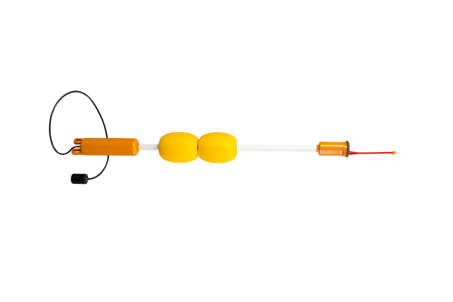
- Four sonobuoys RWLT GIB:
 |
|---|
| RWLT GIB Navigation sonobuoy |
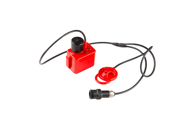
- Navigation solver/radio modem/dongle with built-in GNSS receiver uNav RWLT RF Dongle, for receiving navigation information from buoys:
 |
|---|
| RWLT RF Dongle Navigation solver/radio modem/dongle |
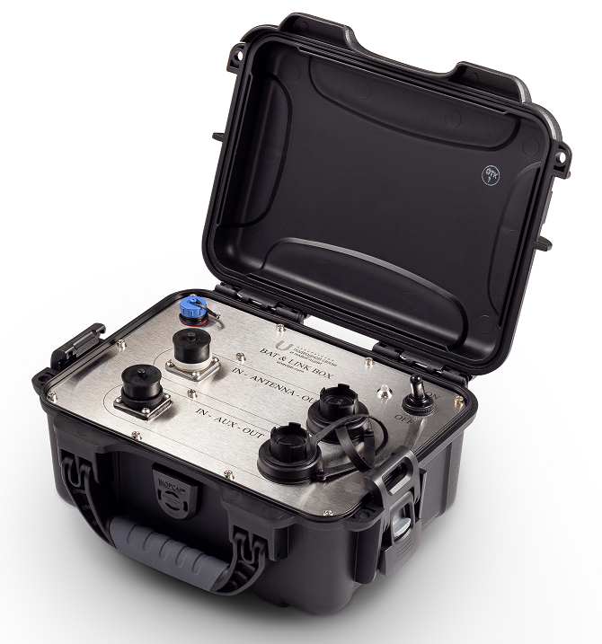
- Autonomous power supply and interface converter Bat&Link Box, to which the radio modem/dongle is connected.
 |
|---|
| Bat&Link Box Autonomous power supply and interface converter |
And, depending on the user task:
- If it is necessary to determine the location of divers simultaneously with voice communication, then up to 255 diver’s telephone stations RedPhone-DX are used;
 |
|---|
| RedPhone-DX Wireless voice communication diver’s station |
In this configuration, the divers’ geoposition will be determined at the moment they release the PTT button, i.e. complete transmission of the voice message; The transmission of voice messages must take place in turns.
- If it is necessary to determine the location of a remotely controlled vehicle (ROV, ROV), or a diver without the need to use voice communication, then 1 pinger beacon RWLT Pinger is used. The pinger works autonomously and the geoposition of the object on which the pinger is attached will be updated every two seconds.
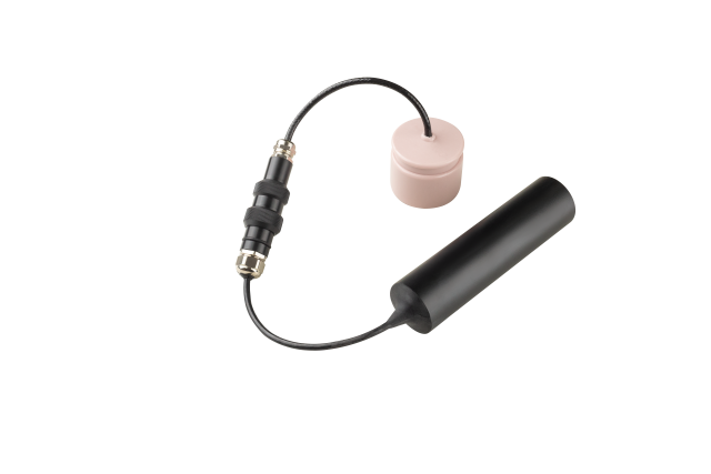 |
|---|
| RWLT Pinger Pinger Beacon |
2. Working with the RWLT system
2.0. Before work
Depending on whether you are working with a pinger or tracking the movements of divers, you will need different versions of specialized software.
-
To track an underwater object equipped with an autonomous pinger RWLT Pinger, the uNav application must be installed on the operator’s PC. Before starting work, be sure to read the short user manual: uNav Application: User Guide
-
To track the position of divers equipped with wireless diver’s telephones RedPhone-DX, the 🤿 uTrackDiver application must be installed on the operator’s PC. Before starting work, be sure to read the short user manual: Appendix 🤿 uTrackDiver: User Manual
Download the necessary software in advance. No installation is required - just unzip the contents of the archive to a location convenient for you.
Regardless of the type of underwater equipment being used - wireless diver’s telephones or an autonomous pinger beacon, make sure that all equipment is fully charged before going out on the water, and if necessary, charge all devices.
Due to the fact that the devices have built-in power supplies based on LiFePO4, they have a very flat discharge characteristic and it is difficult to determine the degree of charge of the built-in source. Therefore, it is recommended to charge all devices no earlier than 1-2 days before use.
2.1. Preparing for work and checking equipment
2.1.2. Checking the buoy set
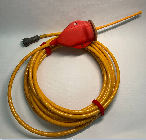
- Make sure that all buoys in the kit are intact, paying special attention to the transducer cable;
- Make sure that all buoys are operational and that their built-in power supplies are sufficiently charged by turning them on by placing the bottom of the buoy in the water;
- Make sure that silicone grease is applied to the bronze contacts of the buoy top unit.
The buoys have a two-color light indication, the LEDs of which are located in the upper part of the device under a layer of transparent compound. One of the indicators is designed to indicate the presence of the device on the water, and lights up briefly once per second, and the other is to inform about the status of the device.
The buoys in each set have different addresses from 1 to 4. When the buoy is turned on, it reports its number in the set using an information indicator: the number of flashes corresponds to the buoy number.
After reporting its number, the buoy goes into operating mode. If the buoy’s battery is charged, the information indicator begins to light continuously until the built-in GNSS receiver detects signals from satellites of the global satellite navigation system. After which it will flash once every 4 seconds. The number of flashes in this case also corresponds to the number of the buoy in the set.
If the buoy battery is in a state where the charge remains less than 20%, the information indicator will flash 1 time per second. The number of flashes in this case also corresponds to the number of the buoy in the set.
If the user notices that both indicators are flashing once per second, the buoy should be turned off and charged as quickly as possible. Long-term operation with a discharged power supply is not permitted.
If the battery is in a state of critical discharge, then after reporting its number the buoy will automatically turn off, in this case both indicators will also be turned off. The buoy must be charged immediately to avoid failure of the built-in power supply.
If everything is done correctly, and the upper parts of the buoys have a good view of the celestial hemisphere, then after some time (usually no more than 1-2 minutes) you will be able to see the positions of the buoys in the main application window.
After this, you can place the buoys on the surface of the water.
2.1.2.1. Charging the built-in power supply
The device is charged using the included accessory and only when the device is turned off and completely dry.
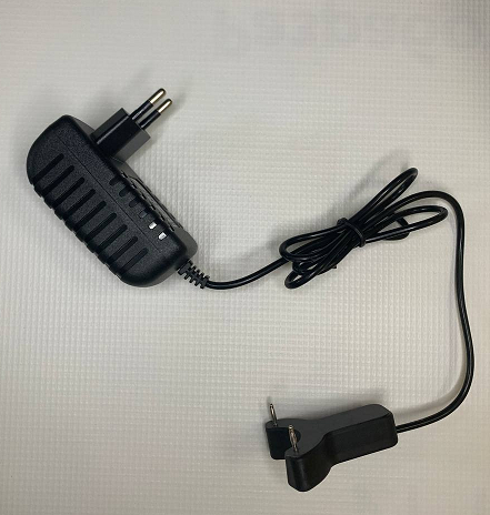 |
| Buoy charger |
Before connecting the accessory to the buoy, turn it off. Make sure that the charging contacts of the accessory fit into the sockets on the buoy, then connect the charger to the mains. Depending on the version of the charger, the indication of operating modes may differ. For more complete information, please refer to the charger instructions.
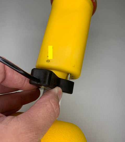 |
| Connecting the charger to the buoy |
 |
| Charger connected |
Once charging is complete, unplug the charger and remove the charging accessory from the buoy.
2.1.2.2. Connecting the service cable
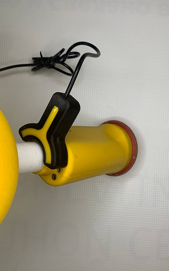
Connecting a service cable may be required to change the buoy’s address, determine its serial number, or update its software. The service cable is connected using the supplied adapter, which is connected to a group of contacts located at the bottom of the surface block of the device. The picture below shows the connection of the adapter.
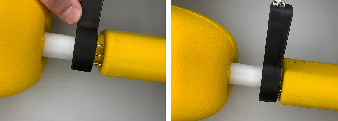 |
| Connecting the service cable adapter |
After connecting the adapter with cable to the buoy, connect it to the PC on which install the required software:
- UCNL_FW_Update for software update
To turn on the buoy, place its lower part in the water so that the contacts of the water detector are in it. After completing the service operations, turn off the buoy and disconnect the service adapter.
2.1.3. Location of buoys on the water surface
Buoys are placed in the water area on the surface of the water, their position is fixed using anchors.
It is worth remembering that although buoys have a slight positive buoyancy, they are not intended to be directly attached to anchor rope. To unload the buoy from the weight of the anchor rope, fenders (or floats) corresponding to the weight of the rope must be used.
The figure below1 shows the recommended installation scheme for a buoy on a pond.
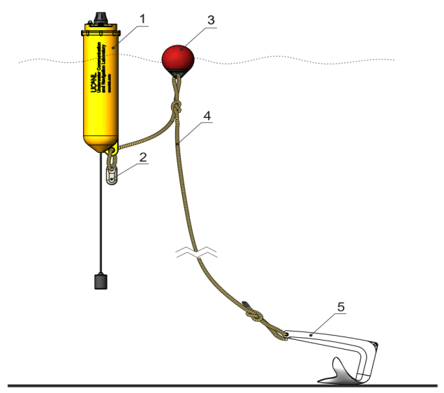 |
| Recommended buoy installation scheme |
| 1 - hydroacoustic navigation buoy, 2 - additional weight2, 3 - float, 4 - anchor rope, 5 - anchor |
1 Images may differ from actual products, since the manufacturer is constantly working to improve characteristics and make changes to the design. 2 Additional weight is used only in the underloaded version.
Buoys should be placed in a convex quadrangle, covering the entire work area with a small margin. It is important to comply with several simple conditions for the system to operate effectively:
- buoys are located no closer than 30 and no further than 1500 meters from each to each
- from each buoy there must be direct visibility to the receiving radio modem of the operator’s console
- from each sonar receiver of the buoy there must be direct visibility to the positioned underwater object
- it is not recommended to place buoys close to the shore, port infrastructure, or ships
- the size of the navigation base (the average size of the rectangle formed by the buoys on the water surface) should not be less than the maximum depth of the positioned object
- the size of the navigation base should be slightly larger than the intended area of work
ATTENTION! Buoys are not underwater devices and are designed to operate on surface water. Although the protection class implies a short-term blocking of the device by the wave, it is worth remembering that the built-in radio equipment (GNSS module and radio modem) cannot operate in such conditions!
It is not recommended to throw buoys overboard. It is necessary to carefully lower them to the surface of the water, while making sure that the length of the anchor rope is sufficient, and its weight is taken by the unloading fender, and the buoy is located vertically on the surface of the water and does not experience any additional loads.
2.1.4. Preparation of underwater equipment
Subsea equipment preparation varies for different system configurations:
- For configuration with location tracking of divers equipped with wireless diver’s telephones RedPhone-DX refer to RedPhone-DX User’s manual.
It should be remembered that:
- the stations must have the RWLT Pinger mode enabled (RWLT Pinger enabled setting);
- when using several voice communication stations in one body of water, they must be given different addresses (RWLT Diver’s ID).
- To configure a system with an autonomous pinger beacon RWLT Pinger no preliminary actions are required except for pre-charging the built-in power source (battery pack). For versions with a detachable connection between the beacon-pinger and the battery pack, you must first make sure that the hermetic connector is tightly closed and serviced (for threaded connectors, make sure that the O-rings are lubricated with silicone grease; for connectors of the SUBCONN type and the like, make sure that grease is applied to both parts of the connector lubricant recommended by the connector manufacturer).
The pinger beacon turns on automatically when it gets into water (the contacts for turning it on from water are located on the battery block). It should be remembered that immediately after turning on, the pinger beacon determines atmospheric pressure within 5 seconds for a more accurate depth measurement. Therefore, it is recommended to first immerse the battery pack in water and wait 5 seconds before immersing the pinger beacon itself.
ATTENTION! All versions of the pinger beacon transmit a navigation signal only in the presence of an excess pressure of more than 50 mBar (approximately corresponding to a depth of 60 cm)
The pinger beacon should be attached only to a special groove with a soft clamp in such a way as to exclude any uneven loading of the beacon body, excessive compression and shading/screening of the beacon body. The figure below shows the basic requirements for installing the acoustic part of the pinger beacon on the carrier:
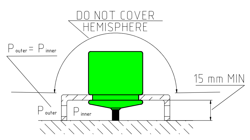 |
| Requirements for installation of the acoustic part of the pinger beacon on the carrier |
| Shielding of the spatial hemisphere or parts of the antenna located above the mounting groove is not allowed; the pressure in the area under the fastening must be balanced with the external pressure |
The functionality of the pinger beacon can be easily checked by lowering it into water: when submerged more than 1 meter, it begins to emit a navigation signal with a period of 2 seconds.
2.1.5. Preparing RF dongle for operation
Before operation, the radio modem must be connected to an autonomous power supply Bat&Link Box. Before using an autonomous power supply, you must read the operating instructions of the autonomous power supply and interface converter.
Connect the radio modem cable to the autonomous power supply Bat&Link Box, and it, in turn, to the PC on which the application corresponding to the system configuration is installed. Then turn on the power supply.
After power is applied, the radio modem turns on the indicator (starts blinking). The radio modem has a two-color light indication. One of the colors lights up synchronously with the arrival of messages from the buoys via the radio channel, thereby signaling the presence of communication with the buoys, and the other lights up at the moment of receiving the next portion of data from the built-in GNSS receiver, and goes out if the data is valid. If it is constantly on, this indicates that the built-in GNSS module has not yet determined its own location.
During normal operation of the system, one of the indicators will blink once per second, and the other should blink four times within 2 seconds - it is during this period that packets from all four buoys should arrive.
2.1.6. Choosing a location for the operator console
Mount the radio modem at the highest possible point so that there is a clear line of sight between the radio modem antenna and all buoys throughout the entire operation of the system. To ensure this condition, the radio modem is equipped with a cable 10 meters long.
The radio modem antenna should not be obscured by any objects that delay the radio signal: elements of the ship’s deck superstructure, side, mast and other radio equipment, trees, building walls, elements of port infrastructure, etc.
2.2. Working with the system
You should remember the factors that reduce the efficiency of the system:
- hydrological conditions: natural and man-made noise can worsen and completely eliminate the normal operation of the system; unfavorable underwater terrain and bottom vegetation can contribute to acoustic shadowing, etc.
- exit of the positioned object(s) beyond the navigation base (the figure formed by buoys on the water surface): the most stable operation of the system is achieved inside the navigation base. To some approximation, the relative position of the diver and the navigation base is estimated by the parameters DOP and TBA. A position in close proximity to or directly behind one of the buoys is also unfavorable.
- large ships, especially those with deep draft, can interfere with the passage of the acoustic signal.
Determining the location of an underwater object or objects (if work is carried out with divers equipped with wireless voice communication diving stations RedPhone-DX is possible when the the following conditions:
- all buoys have GNSS reception, and the operator’s console receives radio signals from all buoys. Those. the application displays the positions of all four buoys;
Additionally, when configuring the system to work with diving stations RedPhone-DX:
- stations are correctly configured to work with the RWLT system;
- a special navigation signal, emitted by the diving station after the diver completes the voice transmission (releasing the PTT button), is received by all four buoys of the RWLT system;
- signals from different divers do not overlap each other, and there is a time interval of at least 2 seconds between signals from different divers;
2.3. Upon completion of work
Navigation buoys must be:
- removed from anchors;
- cleared of contaminants (silt, dirt, algae, etc.);
- desalinated if the work was not carried out in fresh water;
- before placing in the transport case, wiped with a soft cloth to remove moisture;
Not allowed:
- Storage undesalinated;
- Storing buoys together with wet anchor ropes and other wet objects;
Pinger beacon should be:
- removed from the carrier;
- washed from contaminants (silt, dirt, algae, etc.);
- desalinated if the work was not carried out in fresh water;
- gently wiped with a soft cloth and air dried for at least 30 minutes;
Not allowed:
- mechanical impact on the hole of the pressure sensor;
- storage with the presence of moisture (especially sea);
- freezing of water in the hole of the pressure sensor;
Wireless voice communication diving stations Upon completion of work, they do not require any additional manipulations and turn off automatically in the air. Before placing in a shipping container, it is necessary to perform washing and/or desalination in fresh water, followed by wiping with an absorbent cloth and drying for at least 30 minutes in air.
For additional and up-to-date information, please refer to the Instructions for use of diving wireless voice communication stations.
3. Obligations and Disclaimer
3.1. Conditions for replacement and free warranty service
The manufacturer’s warranty applies only to manufacturing defects that appear during operation of the device in accordance with this manual during the warranty period (2 years from the date of purchase).
The manufacturer guarantees free repair or replacement of faulty equipment included in the delivery set that has failed due to a manufacturing defect.
The grounds for refusal of free warranty service, free repair and replacement include:
- any mechanical damage to the equipment supplied, incl. violation of insulation of wires and cables;
- any damage caused by exposure to moisture and dirt due to improper use of the supplied equipment;
- any electrical damage caused by use of incomplete accessories (charger), use of low-quality and/or damaged batteries; Incomplete accessories do not include those supplied by the manufacturer or its representative to replace faulty or lost ones;
- any traces of self-repair and/or opening of the equipment included in the delivery set.
3.2. Manufacturer disclaimer
ANY OF THE PARTS OF THE DELIVERY SET, INDIVIDUALLY AND AS A PART OF THE SYSTEM (hereinafter referred to as the “EQUIPMENT SUPPLIED”):
- NOT DEVELOPED AS MEANS OF RESCUE
- NOT TESTED AS MEANS OF RESCUE
- IS NOT MEANS OF RESCUE
- THE MANUFACTURER DECLARES THAT THE EQUIPMENT SUPPLIED IS SAFE WHEN USE ACCORDING TO THESE INSTRUCTIONS AND IS NOT RESPONSIBLE FOR ANY CONSEQUENCES OF THE USE OF THE SUPPLIED EQUIPMENT
THE MANUFACTURER GUARANTEE THAT THE RWLT HYDRO-ACOUSTIC TRACKING SYSTEM (hereinafter referred to as the SYSTEM):
- DESIGNED ONLY TO WORK WITH PINGER BEACONS OR DIVING COMMUNICATION STATIONS DESIGNED FOR JOINT OPERATION WITH THE SYSTEM
- STRUCTURALLY CANNOT BE USED FOR TRACKING OBJECTS NOT EQUIPPED WITH PINGER BEACONS OR DIVING COMMUNICATION STATIONS NOT DESIGNED FOR JOINT WORK WITH THE SYSTEM
- CONTAINS ONLY CIVIL AND UNLICENSED RADIO MODULES: GNSS RECEIVERS AND RADIOS
THE ABOVE LIMITATIONS CANNOT BE REMOVED BY ANY MANIPULATION WITH THE SETTINGS AND/OR CONTROLS OF THE SYSTEM DEVICES AND/OR THE SOFTWARE INTENDED TO WORK WITH THE SYSTEM