docs.unavlab.com
Main ❯ Underwater wireless voice systems ❯ RedPhone-DX: User’s manual
ℹ Recommendations for printing / saving as PDF
- Press Ctrl+P (macOS: Cmd+P)
- Select "Save as PDF" (Microsoft Print to PDF) as the printer
- In "Pages", enter a range that excludes the first and the last page
- Disable headers and footers (title, URL, page numbers)
- In Chrome/Edge: More settings → "Margins" → None | in Firefox: "Margins & Header/Footer" → None
- Click Print and choose where to save the PDF
 |
|
|---|---|
| www.unavlab.com support@unavlab.com |
RedPhone-DX Diver station for underwater acoustic voice communication User’s manual |
RedPhone-DX
Diver station for underwater acoustic voice communication
User’s manual
Contents
- 1. Description of the RedPhone-DX station
- 2. Working with the device
- 3. Storage and maintenance
- 4. Obligations and disclaimer
1. Description of the RedPhone-DX station
1.1. Purpose
The diver station for underwater acoustic voice communication RedPhone-DX (hereinafter referred to as the station) is intended for:
- wireless exchange of voice messages between divers equipped with diver communication devices that support the same signal parameters as the station;
- wireless exchange of voice messages between divers and the surface dive control point equipped with the RedPhone-OS surface station or other diver communication devices that support the same signal parameters as the station;
- determining the location (tracking) of divers using the long baseline navigation system RWLT.
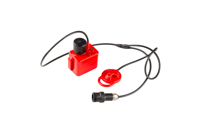
The general view of the RedPhone-DX station is shown in Figure 1.
 |
|---|
| Figure 1 - General view of the RedPhone-DX station |
1.2. Device design
The device is a maintenance-free polyurethane monoblock with built-in LiFePO4 batteries that provide more than 3000 “charge-discharge” cycles. The following are located in the upper part of the device housing:
- underwater acoustic transducer;
- contacts that automatically switch the device on when it enters the water and off when it is removed from the water;
- cable entry with a connector for the communication headset.
Charging is performed with the supplied charger. Channel switching and enabling the compatibility mode with the RWLT navigation tracking system are performed using the supplied service cable.
To ensure the best operating conditions and communication quality, the transducers of the communicating devices must have a direct line of sight to each other. The recommended mounting location for the device is on the tank on the diver’s back. The device must be fastened with a strap or a rubber bungee cord through the mounting eyes. Mounting with a metal clamp is also possible. The cables must not restrict the diver’s movements.
1.3. Technical specifications
The station uses single-sideband amplitude modulation (SSB, Single side band) and supports the bands most commonly used in such systems, which ensures compatibility with almost all similar systems. Any antenna, including an underwater acoustic transducer, has a frequency response that describes its sensitivity at different frequencies; therefore, the device provides slightly different receive and transmit sensitivities on different channels. Table 1 shows the correspondence of the station channel numbers to frequency bands, as well as the degree to which each channel matches the characteristics of the transducer and the transceiver path. Unless there is a pressing need to use a particular channel, for example, to ensure compatibility with devices from other manufacturers, give preference to the channels that best match the characteristics of the transducer.
Table 1 - Correspondence of the channel number and signal parameters
| Channel number | Carrier frequency, Hz | Sideband | Bandwidth, Hz | Match with the characteristics of the transceiver path |
|---|---|---|---|---|
| 1 | 32768 | Lower | 28468 .. 32468 | Good |
| 2 | 32768 | Upper | 33068 .. 37068 | Satisfactory |
| 3 | 31250 | Lower | 26950 .. 30950 | Excellent |
| 4 | 31250 | Upper | 31550 .. 35550 | Good |
| 5 | 28500 | Lower | 24200 .. 28200 | Excellent |
| 6 | 28500 | Upper | 28800 .. 32800 | Excellent |
| 7 | 25000 | Lower | 20700 .. 24700 | Satisfactory |
| 8 | 25000 | Upper | 25300 .. 29300 | Excellent |
The manufacturer is constantly improving the equipment, so the up-to-date technical specifications are given in the device specification:
Table 2 - Links to the current device specification
| Device specification: RedPhone-DX |
1.4. Delivery set
Table 3 - Delivery set
| No. | Name | Quantity | Notes |
|---|---|---|---|
| 1 | RedPhone-DX station with a headset connector | 1 pc. | |
| 2 | Mains charger | 1 pc. | |
| 3 | USB dongle for connecting the station to a PC | 1 pc. |
Figure 2 shows the delivery set
| Figure 2 - Delivery set |
| The numbers indicate: 1 - RedPhone-DX station, 2 - charger, 3 - Service cable |
The connector pinout in the standard version is given in Table 4
Table 4 - Connector pinout
| Pin No. | Function |
|---|---|
| 1 | Microphone |
| 2 | PTT button |
| 3 | Speaker “+” |
| 4 | Speaker “-“ |
| 5 | Tx/Charge “+” |
| 6 | Rx |
| 7 | Common |
2. Working with the device
2.1 Preliminary checks
Before immersing the device in water, the user must make sure that:
- the O-rings (if any) on the headset connector are not mechanically damaged, are not dirty, and are lubricated (in accordance with the manufacturer’s recommendations);
- a headset is connected to the connector (the connector is plugged in);
- the device is securely fastened with a strap to the tank (recommended mounting location) or to the diver’s belt.
Before starting work, the user must:
- check that the communication channels are selected correctly on all devices operating in the immediate vicinity, in accordance with sections 2.2.2 and 2.2.3..
2.2. Operation
Before operation, all the preparations and checks provided for in section 2.1 must be carried out.
Underwater acoustic voice communication with divers is half-duplex: transmission and reception alternate; while the device is in transmit mode, it cannot receive incoming messages.
2.2.1. Sound signals
The possible sound alerts are summarized in Table 5.
Table 5 - Sound alerts
| Alert description | What it signals |
|---|---|
| Short rising and then falling tone | The station is switched on |
| Short rising tone | Switch to receive mode (when the navigation function is off) |
| Short falling tone | Switch to transmit mode |
| Short falling tone (~ every 30 seconds) | Low charge of the built-in power supply |
2.2.2. Receiving voice messages
To receive voice messages from divers, the PTT button on the headset must be released. Incoming messages are then played through the headset.
The volume of incoming voice messages depends on the distance between the station transducer and the diver, as well as on the hydrological conditions. It may decrease when a diver enters an acoustic shadow zone (when elements of the underwater landscape, parts of structures, vessels, algae, etc. are in the signal path).
2.2.3. Sending voice messages
To send a voice message, perform the following steps:
- Press the PTT button on the headset;
- The station emits a short beep, indicating that the device is switching to transmit mode;
- Pause briefly (~0.5 seconds) to let the station switch to transmit mode;
- Speak the voice message clearly, with distinct articulation; it is recommended to end the voice message with the word “Over!” to signal to the recipient that the message has ended;
- Pause briefly (~0.5 seconds);
- Release the PTT button;
- If the compatibility mode with the RWLT navigation system is disabled, the station emits a short beep, indicating that the device has switched to receive mode; if the compatibility mode with the RWLT navigation system is enabled, the station emits a navigation signal through the underwater acoustic transducer.
2.3. Shutdown
After operation, the diver station does not require any additional actions: it switches off automatically in air. Before placing the station in the transport case, rinse and/or desalinate it in fresh water, then wipe it with an absorbent cloth and let it dry in air for at least 30 minutes.
3. Storage and maintenance
3.1. Storage and maintenance conditions
The station has no special storage requirements, except for the following:
- Storage at a temperature from -20 °C to 60 °C;
- The headset connector must be disconnected;
- For long-term storage (more than a month), it is recommended to recharge the built-in power supply of the station;
- To remove contamination from the device housing and after working in seawater, rinsing in fresh water is necessary. A weak solution of household detergents may be used with the battery compartment cover closed; when rinsing, avoid getting moisture and/or detergents into the open headset connector;
- Bending the cables to a radius of less than 5 cm is not allowed;
- Applying torsional forces to the underwater acoustic transducer or the cable entry is not allowed;
- Before placing the device in the transport case, all moisture must be completely removed from it.
PROHIBITED:
- OPENING THE EQUIPMENT FROM THE DELIVERY SET LISTED IN section 1.4.
- ALLOWING PERSONS WHO ARE NOT FAMILIAR WITH THESE INSTRUCTIONS TO USE THE EQUIPMENT FROM THE DELIVERY SET LISTED IN section 1.4.
- ALLOWING PERSONS WHO HAVE NOT REACHED THE AGE OF MAJORITY TO USE THE EQUIPMENT FROM THE DELIVERY SET LISTED IN section 1.4.
3.2. Charging the built-in power supply
The built-in power supply of the station may be charged only with the supplied charger, connected via the connector. Before using the charger, read the charger’s operating instructions. To charge the device, connect it to the supplied charger, then connect the charger to a household power outlet. The end of charging is shown by the indicator on the supplied mains charger. After the indicator on the mains adapter shows that charging has finished, it is recommended to leave the device on charge for another 1–1.5 hours.
3.3. Station configuration
The following can be configured on the station:
- one of the supported communication channels from Table 1
- compatibility mode with the RWLT tracking system
- Address (diver identifier) for the tracking system
- Channel identifier of the RWLT system (reserved for future versions, must be 0)
- VAD (Voice Activity Detector) sensitivity and volume of the alert signals
The station is configured by connecting it to a PC or using an Android-based device. In both cases, connect the station to the device using the USB service cable and switch the station on. When connecting to a smartphone or tablet running Android or HarmonyOS, an additional USB adapter, which is not included in the delivery set, may be required.
3.3.1. Step 1
To configure the station using an Android or HarmonyOS device, download and install the latest version of the UCNLLauncher application.
To configure the station using a PC, use the online utility (PWA) RedPhone DX Config. The online utility requires a Chromium-based browser, such as Google Chrome, Edge, Vivaldi or Opera. If you need to configure the station using a PC without an Internet connection, you can save the application locally by downloading the archive and unpacking it to a convenient location. To launch it, open index.html.
3.3.2. Step 2
Disconnect the service cable from the PC or the Android/HarmonyOS device if it is connected.
3.3.3. Step 3
If you are using a PC, open the RedPhone DX Config application page. If you are using an Android/HarmonyOS device, launch the UCNLLauncher application.
3.3.4. Step 4
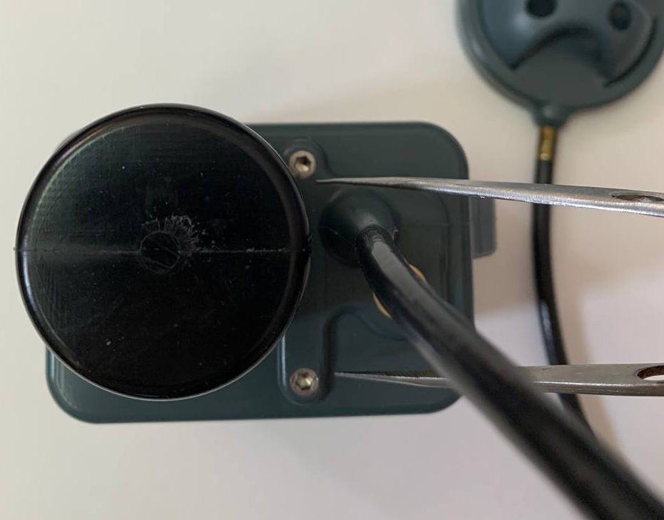
Connect the service cable to the RedPhone-DX station and switch the station on. To switch the device on without immersing it in water, you can place a wet wipe on the contacts shown in the figure:
 |
|---|
| Contacts for switching the device on |
You can short the contacts with a metal object, provided that the connection is reliable: if the contact between the conductors is lost, the station will switch off instantly. You can also put the device in a container of water with the transducer down so that only the transducer and the contacts are covered with water.
Make sure that the contact is reliable and the station is switched on: you will hear the switch-to-receive-mode tone in the headphones. If the channel number display setting is enabled, the seven-segment indicator on the top surface of the device will blink 1 time per second, showing the current communication channel number.
3.3.5. Step 5
Connect the service cable to the PC or to the Android/HarmonyOS device. In some cases, it may be necessary to install a driver for the USB converter.
On the PC, press the “Connect” button in the application, after which the browser will display a port selection dialog. Select the required port (usually USB Serial Port (COMXX), where XX is the port number). Then press the “Connect” button.
| Step 5a (PC) |
On an Android/HarmonyOS device, in the UCNLLauncher application, press the RedPhoneDXConfig button. Then press the “Connect” button.
Allow the application to access USB. The application may request access to geolocation, which is required by other applications, for example AzimuthWebSuite. Access to geolocation is not required for configuring RedPhone-DX diver stations.
| Step 5b (Android/HarmonyOS) |
3.3.6. Step 6
If the station is switched on and the connection is established, the application screen will display information about the device:
In the “Connection” section:
- Device type
- Serial number
- Firmware version
- Current settings
| Step 6 |
In the “SETS2 Settings” section:
- Communication channel number from Table 1
- Volume of the sound effects (when switching to receive/transmit mode, when the charge of the built-in power supply is low)
- VAD (Voice Activity Detector) sensitivity
- Threshold for the low charge alert of the built-in power supply
- Tracking function enabled/disabled flag (RWLT Mode).
The “Flags” subsection contains low-level device settings.
- Bit 0 (PinsPrevail). If the function is active, the device will ignore the communication channel settings (the channel will always be 1).
- Bits 1 to 6 are reserved for future versions
- Bit 7 (CH Indicator). If the function is active, the device uses the seven-segment indicator to display the current communication channel number and to indicate a low charge of the built-in power supply. When the voltage is below the set threshold, the indicator blinks 2 times per second. At normal voltage, it blinks 1 time per second.
After changing the settings, transfer them to the device by pressing the “Save Settings” button.
CAUTION! For the settings to be saved in the internal flash memory of the device, the “Write to Flash” checkbox must be selected.
We recommend using channel 8, because the frequency band used in this channel allows the most efficient use of the analog path of the RedPhone-DX and RedPhone-OS stations.
When diving together, always check carefully that all devices are set to the same channel!
The RWLT Mode checkbox controls the built-in diver tracking function. When the tracking function is enabled, at the end of each voice transmission from a diver (after the PTT button is released), the station will emit a special navigation signal that is received by the buoys of the RWLT system, which makes it possible to determine the geographic position of the diver.
The RWLT Diver ID input field sets the address (identifier) of the diver that will be displayed on the map.
When working with the RWLT system, it is very important to set a different address on each diver station, otherwise the locations of different divers with the same addresses will be displayed as a single track.
If you do not plan to use the RWLT tracking system, be sure to clear the RWLT Mode checkbox: this will save battery power and eliminate the additional pause after a voice transmission during which the navigation signal is emitted.
4. Obligations and disclaimer
4.1. Terms of replacement and free warranty service
The manufacturer’s warranty applies exclusively to factory defects detected during operation of the device in accordance with this manual during the warranty period (2 years from the date of purchase).
The manufacturer guarantees free repair or replacement of faulty equipment from the delivery set that has failed due to a factory defect.
The grounds for refusing free warranty service, free repair and replacement include:
- any mechanical damage to the equipment from the delivery set specified in section 1.4., including damage to the insulation of wires and cables;
- any damage caused by exposure to moisture and contamination due to improper use of the equipment from the delivery set specified in section 1.4.;
- any electrical damage caused by the use of accessories not included in the delivery set (charger), or by the use of poor-quality and/or failed batteries. Accessories supplied by the manufacturer or its representative to replace faulty or lost ones are not considered to be outside the delivery set;
- any traces of unauthorized repair and/or opening of the equipment from the delivery set specified in section 1.4..
4.2. Limitation of the manufacturer’s liability
ANY PARTS OF THE DELIVERY SET LISTED IN section 1.4., SEPARATELY AND AS PART OF A SYSTEM, HEREINAFTER REFERRED TO AS THE “SUPPLIED EQUIPMENT”:
- WERE NOT DEVELOPED AS A MEANS OF RESCUE;
- WERE NOT TESTED AS RESCUE EQUIPMENT;
- ARE NOT RESCUE EQUIPMENT.
THE MANUFACTURER DECLARES THAT THE SUPPLIED EQUIPMENT IS SAFE WHEN USED IN ACCORDANCE WITH THESE INSTRUCTIONS, AND IS NOT RESPONSIBLE FOR ANY CONSEQUENCES OF THE USE OF THE SUPPLIED EQUIPMENT.