docs.unavlab.com
Main ❯ Navigation & tracking systems ❯ Zima USBL: Data brief
ℹ Recommendations for printing / saving as PDF
- Press Ctrl+P (macOS: Cmd+P)
- Select "Save as PDF" (Microsoft Print to PDF) as the printer
- In "Pages", enter a range that excludes the first and the last page
- Disable headers and footers (title, URL, page numbers)
- In Chrome/Edge: More settings → "Margins" → None | in Firefox: "Margins & Header/Footer" → None
- Click Print and choose where to save the PDF
 |
 |
|---|---|
| www.unavlab.com support@unavlab.com |
Zima USBL Data brief |
General information
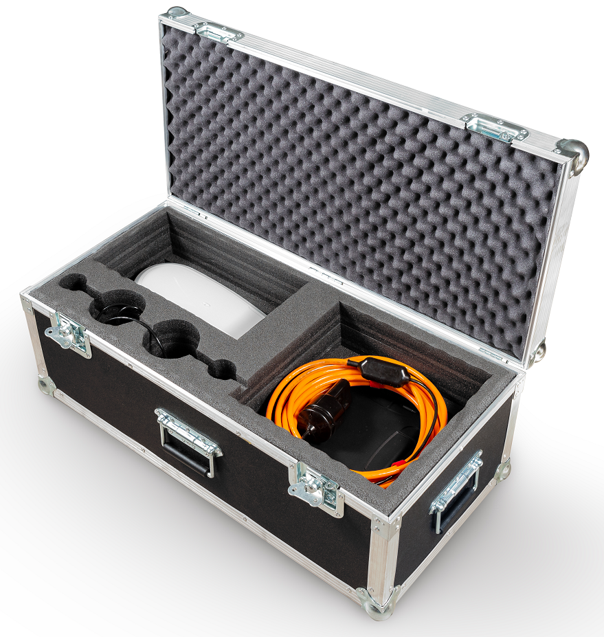
Zima USBL is an underwater acoustic ultra-short baseline (USBL) navigation system designed to determine the location of underwater objects marked with underwater acoustic responder-beacons Zima-R using a direction-finding transceiver antenna Zima-B.
System composition
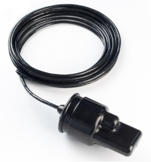 |
Zima-B Direction-finding base station |
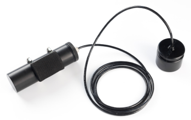 |
Zima-R Responder-beacons (one base station can work sequentially with a maximum of 23 responders) |
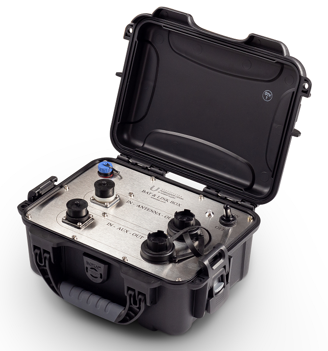 |
Bat&Link Box Autonomous power supply and switching unit for the base station |
Tasks to be solved
- Determining the location of up to 23 underwater objects in the water area (tracking underwater objects)
- Determining the relative location (azimuth, distance, depth)
- Determining the absolute location (latitude, longitude, azimuth, distance, depth) when connected to an external GNSS and compass (or GNSS with compass function)
- Mutual navigation: transmitting to the beacon the azimuth to the direction-finding antenna and measuring by the beacon the distance to the antenna (when the beacon is data-interfaced with the carrier and when an external compass or GNSS with compass function is connected to the host PC);
- Remote control: transmitting up to 32 code commands to underwater objects (when the beacon is data-interfaced with the carrier);
Distinctive features
- Compactness, long range and maximum ease of use make it possible to use the Zima system to work with various ROVs and AUVs, as well as with divers, in any combination
- The highly versatile beacons can be used either in a standalone version with a separate battery pack or interfaced with the carrier for both power and data; in this case, it is possible to transmit up to 32 addressed code commands for remote control of the underwater object
- The system supports integration with external sources of navigation data: GNSS and a magnetic compass (connected to the host PC). In this case, the system determines the absolute geographic coordinates of underwater objects, allows saving the track of movement of underwater objects and has GPS emulation functions for one of the selected beacons for integration with third-party software (for example, Hypack, SAS.Planet, etc.)
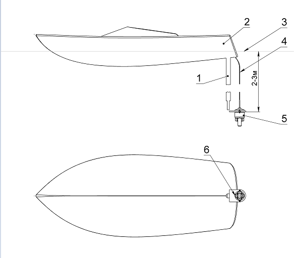
- The Zima-B antenna is mounted on a pole over the side of almost any vessel and connected to a 12 V / 3.5 A power source and to a host PC (Windows 7 or later) – in this minimum configuration, the system determines the position of the beacons (azimuth and distance) relative to the antenna. When a GNSS receiver (RMC, GGA) and a magnetic compass (HDG) are connected to the host PC, the system determines the geographic coordinates of the beacons and can transmit them (RMC, GGA) to any serial port, thereby emulating a GNSS receiver;
- Instead of a magnetic compass, a GNSS system with several antennas can be used (HDT sentences);
 |
|---|
| Installation diagram of the Zima-B antenna 1 - pole, 2 - vessel, 3 - water surface, 4 - cable, 5 - antenna Zima-B, 6 - antenna direction |
Interfacing schemes
Working in relative coordinates
To determine the relative location of the responder-beacons, the antenna is interfaced with a PC on which specialized open-source host software ZHost is installed. The antenna is connected to the PC via Bat&Link Box, which converts the interface to USB and powers the antenna.
In this case, the data and functions available to the user are:
- Azimuth (horizontal angle) to the responder-beacons in use;
- Distance to the responder-beacons
- Depths of the responder-beacons
- Possibility of addressed transmission of up to 32 code commands to each beacon (when the beacons are data-interfaced with the carrier)
 |
|---|
| Wiring diagram for working in relative coordinates |
Working in absolute coordinates
To determine the absolute location of the responder-beacons, the antenna is interfaced with a PC on which specialized host software ZHost is installed. The antenna is connected to the PC via Bat&Link Box, which converts the interface to USB and powers the antenna. Additionally, an external GNSS system and a magnetic compass operating via the NMEA 0183 protocol (RMC and HDG sentences), or an external GNSS system with compass function operating via the NMEA 0183 protocol (RMC and HDT sentences), are connected.
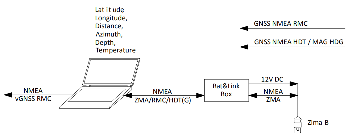 |
|---|
| Wiring diagram for working in absolute coordinates |
In this case, the following data and functions are available to the user:
- Absolute geographic coordinates of the beacons and depth
- Azimuth (relative to north)
- Distance
- Possibility of addressed transmission of up to 32 code commands to each beacon (when the beacons are data-interfaced with the carrier)
- Recording a track of the movement of underwater objects with the possibility of subsequent saving in Google KML format.
Geometric limitations
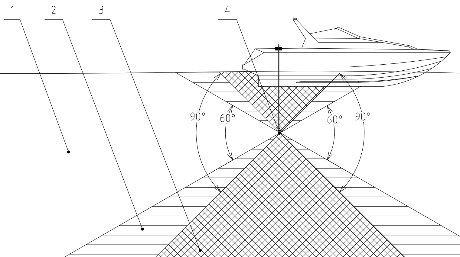
Since the location of the responder-beacons Zima-R is determined from the horizontal angle of arrival of the signal, the slant range and the depth difference, the antenna array of the direction-finding station Zima-B has the highest sensitivity in the horizontal plane. This imposes geometric limitations on the relative positions of the direction-finding antenna and the responder-beacon. The operating vertical angle of the antenna is +/- 30° from the horizontal plane. Operation is possible, but not recommended, at such relative positions of the antenna and the responder-beacon that the vertical angle to the beacon is in the range from 30° to 45°, because the accuracy of determining the angle of arrival of the signal decreases. Operation at vertical angles to the beacon above 45° is strongly discouraged.
 |
|---|
| Geometric limitations of Zima-B 1 - working zone (+/- 30°), 2 - accuracy reduction zone (30 .. 45°), 3 - shadow zone ( > 45°), 4 - direction-finding antenna. The deviation is indicated from the horizontal plane passing through the center of the antenna array |
The export version of the system differs in the transceiver path and has a smaller operating range (3000 m).