docs.unavlab.com
Main ❯ Navigation & tracking systems ❯ Zima2 USBL: User’s manual
 |
|
|---|---|
| www.unavlab.com support@unavlab.com |
Zima2 USBL - Underwater acoustic tracking system User’s manual |
Zima2 USBL
User’s manual
Contents
- 1. Introducation
- 2. Working with Zima2 USBL system
- 3. Liability and Disclaimer
1. Introducation
1.1. Purpose
The Zima2 underwater acoustic tracking system is designed to locate underwater objects equipped with Zima2-R responder beacons in real time.
Beacons-responders (hereinafter beacons) can be installed on:
- remotely controlled underwater vehicles (RTUV)
- manned underwater vehicles (OPA)
- autonomous uninhabited underwater vehicles (AUVs)
- divers and technical divers (in case of using the autonomous version of beacon).
The system allows you to determine:
- relative location of underwater objects (azimuth angle, range, depth)
- absolute location of underwater objects (latitude, longitude, depth) when using external sources of navigation data (GNSS receiver and compass).
1.2. Distinctive features
The navigation system Zima2 is an ultra-short-base navigation system (USBL), the principle of operation of which is based on the use of a phased antenna array to determine the horizontal angle of arrival of the signal and determine the distance to the beacon using the “request-response” method. The Zima2 system uses state-of-the-art digital broadband noise-resistant hydroacoustic communication technology, and the applied signal is specially Designed for difficult hydrological conditions, including those found in shallow waters.
1.3. System Composition
The system includes:
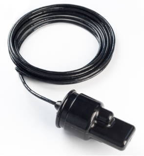
- DF antenna Zima2-B
- Cable with integrated interface converter
- From 1 to 16 responder beacons Zima2-R
- Power supply and switching unit Bat&Link Box.
 |
|---|
| Zima2-B |
| DF Antenna |
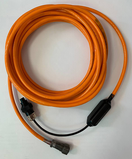 |
| Cable with integrated interface converter |
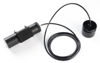 |
| Zima2-R |
| Beacon-responder |
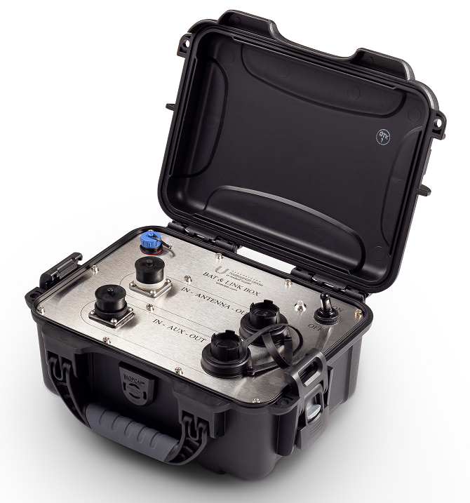 |
| Bat&Link Box |
| Power supply and switching unit |
2. Working with Zima2 USBL system
2.0. Before start
Specialized software 🐙 AzimuthSiute is required to work with the system.
Download the necessary software in advance. Installation is not required - just unzip the contents of the archive to a location convenient for you. Make sure all equipment is fully charged before heading out to the water and charge all devices if necessary.
Particular attention should be paid to power and switching units and responder beacons: in view of the fact that these devices have built-in power supplies based on LiFePO4, they have a very flat discharge characteristic and it is difficult to determine the degree of charge of the built-in source. Therefore, it is recommended to charge all devices no earlier than 1-2 days before use.
We use LiFePO4 based batteries because they are the most durable and withstand the maximum number of charge-discharge cycles compared to Li-ion and Li-Po batteries, and can also operate at low temperatures.
2.1. Preparing for work and equipment testing
2.1.1. DF Antenna mounting and setup
WARNING!
UNLIKE THE PREVIOUS VERSION OF THE SYSTEM, THE POSITION OF THE ZERO DIRECTION OF THE ANTENNA HAS BEEN CHANGED!
If you hold the antenna by the cable so that there is a rounded protrusion on the mounting groove on the left and a sharp protrusion on the right, then the zero direction of the antenna points forward and coincides with the molding seam. The zero direction is indicated by an arrow in the figure below.
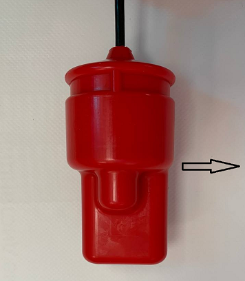 |
|---|
| DF antenna zero direction |
| The horizontal angle is measured clockwise from the zero direction of the antenna, the vertical axis is pointing down |
The antenna determines the horizontal angle of signal arrival relative to its zero direction, the following requirements must be observed when mounting the antenna:
- The antenna should be placed on a lowering rod, ensuring its stable position no closer than 2 meters from the surface of the water and no higher than 1.5 from the bottom of the vessel’s keel
- The antenna must be fixed with a clamp in such a way that its position does not change during operation (the antenna must not rotate inside the clamp)
- The antenna should not be strongly squeezed by the mount
- The mount and its parts must not protrude below the mounting groove and thus overlap the working surfaces of the antenna
- The mount and its parts must not block the opening of the pressure sensor
- A thin cable coming out of the antenna should not be bent with a radius of less than 50 mm, a thick cable - with a radius of less than 100 mm.
It is not recommended to install the antenna near large underwater objects: mooring walls, piers, breakwaters, large ships, massive supports and other water infrastructure facilities.
The antenna is connected to the power supply and switching unit using an extension cable with an integrated interface converter. There are two connectors on the cable: one for connecting to the power supply and switching unit, the other - underwater, for connecting the antenna.
Before submerging the antenna, make sure:
- In the absence of moisture, traces of corrosion and contamination in both parts of the underwater antenna connector
- In the integrity of the seals on both parts of the underwater connector
- The presence of a sufficient amount of thick silicone grease on the seals of the underwater connector
- That the connector is closed and the fastening ring is tightly screwed on by hand
WARNING!
Water ingress into any connectors is completely unacceptable and will result in non-grant damage!
The extension cable must not have large free sags for the length of its immersion in water. It is recommended to fasten the cable to the rod with a rope or nylon ties.
WARNING!
Before connecting the antenna to the power and switching unit using an extension cable, make sure that the power supply is switched off!
The following sequence of actions is recommended when installing the antenna:
- check underwater connector of antenna
- connect the antenna to the extension cable by closing and screwing the underwater connector
- install the antenna in the clamp
- fasten the cable to the rod using nylon ties or pieces of rope at points located at least 500 mm apart
- make sure that the power supply and switching unit is turned off
- connect the topside connector of the extension cable to the power supply and switching unit
- connect the power supply and switching unit to the PC using a USB-B cable
The dual channel power supply and switching unit (for connecting an external GNSS compass) requires additional steps:
- connect the GNSS compass to the supplied cable
- connect the GNSS compass cable to the power and switching unit
Turning on the power supply and switching must be performed after launching the specialized software on the control PC. Software operation and setup are described below.
To clarify the names of the connectors on the power and switching unit panel, refer to the Bat&Link Box power and switching unit user’s manual.
2.1.2. Mounting of the responder beacon on the carrier
The responder beacon must be fastened only by special groove with a soft clamp in such a way as to exclude any uneven loading of the beacon body, excessive squeezing and shading/shielding of the beacon body. The figure below shows the basic requirements for mounting the acoustic part of the transponder beacon on the carrier:
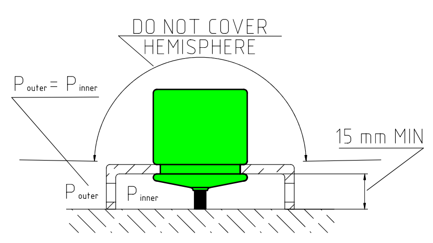 |
|---|
| Requirements for mounting the acoustic part of the transponder beacon on the carrier |
| * Shielding of the spatial hemisphere or parts of the antenna located above the mounting groove is not allowed; the pressure in the area under the fastening must be balanced with the external pressure* |
The responder beacon should not be located near propulsion jets or directly in their path. The system requires a direct line of sight (through the water column) between the direction finding antenna and the responder beacon, so the beacon must be installed at the top of the carrier.
For autonomous responder beacon: The standalone beacon is turned on automatically when it falls into water (contacts for switching on from water are located on the battery pack). It should be remembered that immediately after switching on, the beacon determines atmospheric pressure for 5 seconds for more accurate depth measurement. Therefore, it is recommended to submerge the battery pack first and wait 5 seconds before submerging the responder itself.
For an integrated responder beacon: The integrated version of the responder beacon is switched on when power is supplied from an external system. Once turned on, the responder detects barometric pressure for 5 seconds for more accurate depth measurement. If the current value of the external pressure is more than 1200 mbar, then the beacon considers that it was switched on in the submerged position, and the atmospheric pressure calibration does not take place.
The operability of the beacon-responder can be easily checked by turning it on: after the power is turned on, after 2 seconds, a navigation signal is emitted once.
2.1.3. Testing responder beacons
A functioning responder beacon emits a navigation signal when power is applied. In a noisy environment, you may not hear it, so keep it no more than 20 cm away from your ear when powering up. When using an autonomous beacon-responder, you can also use this test to check the battery’s performance: connect the beacon-responder to its battery and simultaneously touch both metal parts of the connector with a wet hand. If both beacon-responder and its battery is functioning properly a brief (~0.1 sec) hiss will be emmited by the beacon-responder.
2.2. Working with the system
The system performs almost all the work automatically, the system needs to set:
- addresses of beacons with which it is supposed to work
- salinity of water, for the correct calculation of the depth and speed of sound
- the maximum range at which the beacons can be located from the direction-finding antenna
- parameters for connecting an external source of navigation data (GNSS compass) if necessary
- parameters for connecting an external receiver port for GNSS emulation for the selected responder beacon (if an external GNSS compass is available).
Next, the system automatically polls responder beacons from the specified address range. Displays their position on the screen, and records the track in absolute coordinates, in the presence of an external GNSS compass.
During operation, the application writes log files, which can then be played back in the same time scale in which they were recorded.
2.2.1. Interface and functions of the AzimuthSuite application
The application 🐙 AzimuthSiute is designed to work under OS Windows starting from version 10 and higher with .NET Framework 4.8 installed. The application is portable and does not require installation. It is enough to unpack the archive to a place convenient for the operator. The application and all the libraries used by it are developed by LLC “Laboratory of Underwater Communications and Navigation” and are Open-Source.
The application communicates with the system devices according to the open NMEA-like protocol via the serial port.
2.2.1.1. Application settings
The application uses two types of settings:
- basic system settings, which are stored in the
AzimuthSuite.settingsfile in the application directory. These settings are read by the application at startup and saved at the user’s command from the settings editor. - interface settings, which are stored in the
AzimuthSuite.uisettingsfile in the application directory. These settings are read by the application at startup and saved automatically when the application ends.
The appearance of the application settings editor window is shown in the figure below.
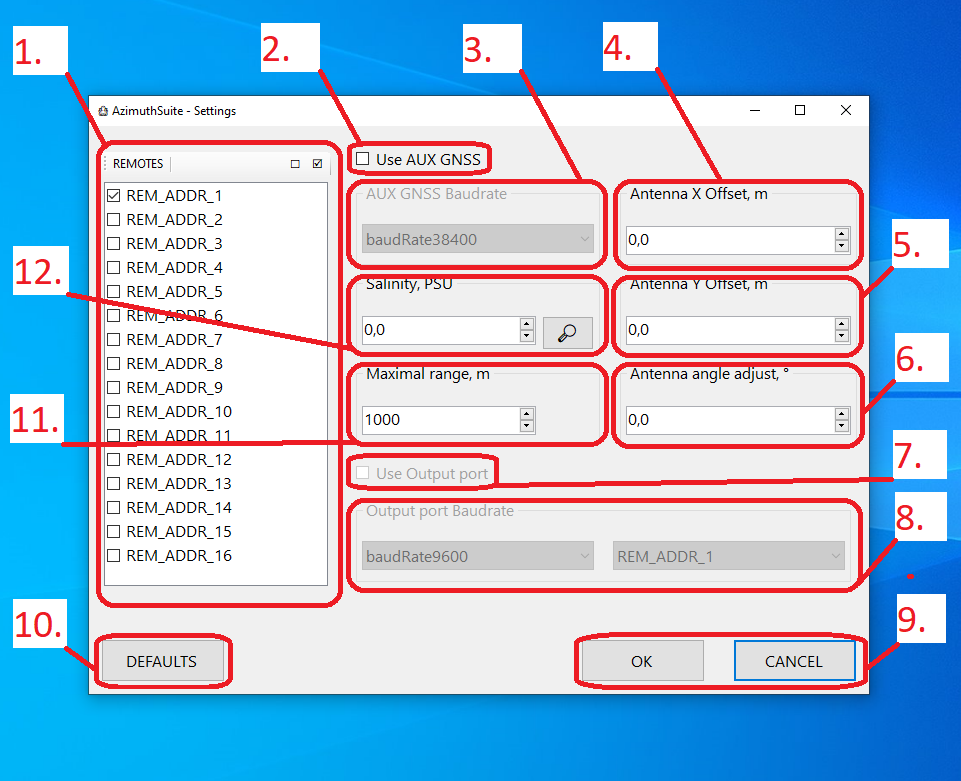 |
|---|
| Settings editor |
| 1 - List of used responder beacons, 2 - External GNSS compass usage option, 3 - External GNSS compass port speed, 4 - Antenna position offset from GNSS compass position in transverse direction, 5 - Antenna position offset from GNSS compass position Longitudinal direction, 6 - Angle correction (angle between GNSS compass zero and antenna zero), 7 - Output port usage option, 8 - Output port speed, 9 - Accept settings and cancel buttons, 10 - Reset settings to default values button, 11 - Maximum distance to responder beacons, 12 - Water salinity |
The system supports sequential operation with up to 16 responder beacons. The operator can select the required beacon addresses in the 1 box by checking the corresponding checkboxes. Always check the boxes next to those addresses that will be used in the current work, otherwise the system will waste time polling beacons that are not in the water area.
Connection of an external GNSS compass is supported via serial port. To do this, check the 2 checkbox and specify the port speed. The port itself will be determined automatically by the system. If the compass is not installed coaxially with the antenna (not on the boom), you will need to set the position of the antenna relative to the position of the GNSS compass: the position of the GNSS compass is taken as the reference point of the Cartesian coordinate system and the lateral 4 and longitudinal 5 offsets are indicated antennas from this point (transverse in the direction of the port side - starboard side, longitudinal in the direction of the stern - bow). If the zero directions of the compass and the antenna do not match, you must specify the angular correction 6 - the angle between the zero directions of the compass and the antenna, counted from the zero direction of the compass clockwise.
The location of the DF antenna in relation to the anchor point is illustrated below:
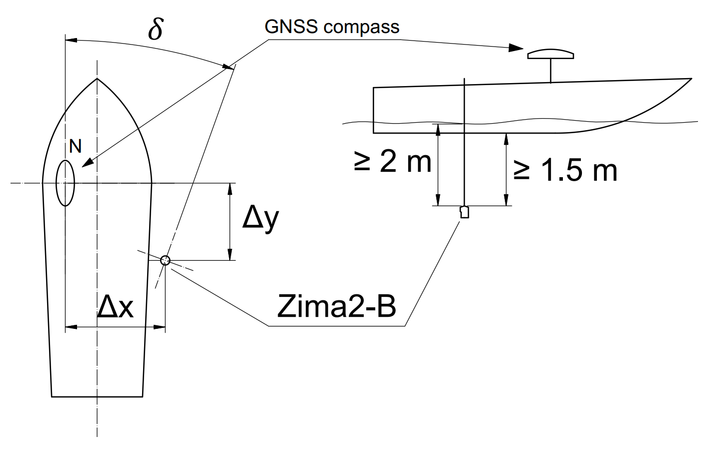 |
|---|
| Setting the location of the direction finding antenna relative to the anchor point and compass zero direction |
| Antenna offsets relative to the GNSS compass: lateral ΔX and longitudinal ΔY; angular mismatch of zero directions of compass and direction-finding antenna 𝛿 |
When working in sea water, specify the salinity using the 12 group of elements: either by entering a known value in the input field or using the built-in database of world ocean salinities by pressing the 🔎 button and indicating the current geographical coordinates .
When operating in inland fresh waters set the water salinity to 0.0 PSU. The salinity value is necessary for the system to more accurately determine the depth and speed of sound.
Maximum distance to the beacon is set in the 11 field and determines the maximum time interval for waiting for the beacon’s response. The value is set in the range from 500 to 5999 meters. The minimum applicable value for the current operating conditions should be specified, since this value directly determines the speed of the system and its idle time when the response of the responder beacon is missed.
If you want to transmit the computed geographic location of one of the responder beacons as standard NMEA (GGA, RMC) messages to another system, enable setting 7 and specify the name and speed of the port to which the application will transmit data. Since the port is used only for transmission, it cannot be determined automatically and its name must be specified.
When you press the OK button, the application will save the settings and prompt you to restart for the new settings to take effect.
2.2.1.2. Main window
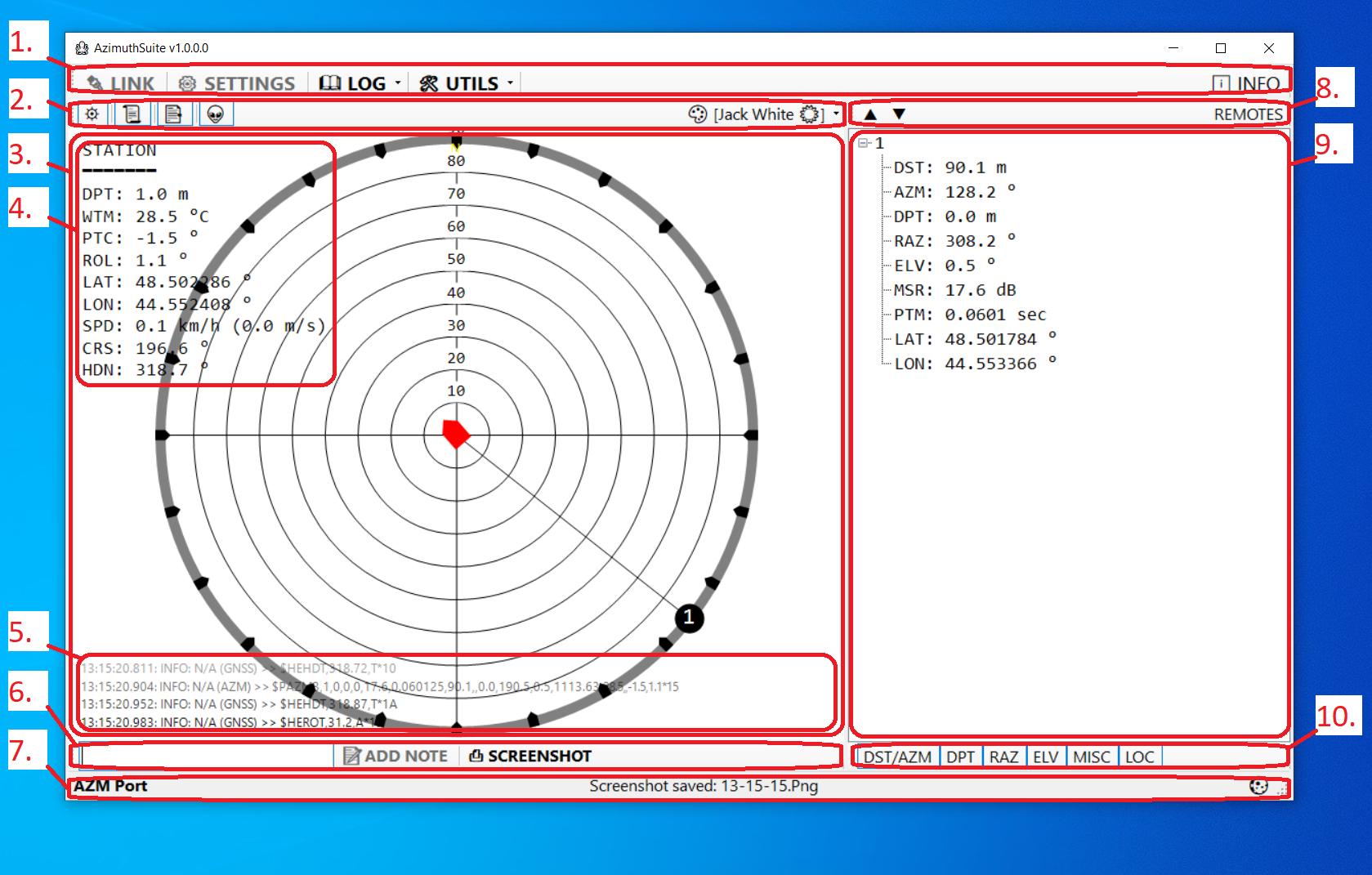
The view of the main window of the application is shown in the figure below.
 |
|---|
| View of the main application window |
| 1 - Main toolbar, 2 - Map toolbar, 3 - Map field, 4 - Misc info text field, 5 - Log text field, 6 - Additional toolbar, 7 - Status bar, 8 - Responder beacon list toolbar , 9 - List of responder beacons, 10 - Switch panel of parameters displayed in the list of responder beacons |
- 1. The main toolbar is located at the top of the application window and contains the following elements:
- The 🔌 LINK button turns on and off the connection with all devices. When the connection is enabled, the application will search for the connected Zima2-B DF antenna and external GNSS compass (when the setting is enabled). This feature is also available via the
Ctrl + Lkey combination. - The ⚙ SETTINGS button is used to open the settings editor. It becomes inaccessible when the connection is active and when the log file is actively replayed.
- Menu 📖 LOG - contains functions for working with log files
- Item 👀 View current - open the current log file in the application associated with the ‘log’ extension (usually Notepad). This function is also accessible via the key combination
Ctrl + H - Item ▶ Playback… - select a log file for real-time playback. This function allows you to almost completely restore the progress of the work done and, for example, restore a track that has not been saved.
- Item 🧹 Clear empty entries - cleaning the LOG directory in the application folder: all log files less than 2 kilobytes in size and all empty folders will be deleted
- Item 🗜 Archive all entries… - packing the entire folder with log files into a Zip archive.
- Item 🗑 Delete all entries - delete all application log files. Be careful! All files will be permanently deleted!!!
- Item 🧹+🗜+🗑 Do them all… - Deleting all empty folders, log files less than 2 kilobytes, packing the rest of the log files into a Zip archive and deleting the originals in the LOG folder of the application.
- Item 👀 View current - open the current log file in the application associated with the ‘log’ extension (usually Notepad). This function is also accessible via the key combination
- Menu 🛠UTILS
- 🗺 TRACKS submenu contains functions for working with tracks
- The 💾 Export… item is used to save tracks in Goole KML or CSV (Comma-separated values) format. This function is available with the key combination
Ctrl + S - Submenu 🤖 DEVICE
- The View info… item is active only when the connection is active and the device is connected (DF antenna or responder beacon) and serves to open a window with information about the device: type, firmware version and serial number
- The Responder settings… item is active only when the connection is active and the responder beacon is connected. Serves to call the editor of the responder beacon settings. The function is also available with the key combination
Ctrl + R
- The 💾 Export… item is used to save tracks in Goole KML or CSV (Comma-separated values) format. This function is available with the key combination
- 🗺 TRACKS submenu contains functions for working with tracks
- The group of elements for controlling the output port contains:
- Button 🔄 to update available serial ports
- Drop-down list of available ports to use as output
- Drop-down list of addresses of beacons-responders, whose coordinates must be transmitted to the output port
- Button 📣 on/off output port
- Button ℹ INFO is used to open the window with information about the application
- The 🔌 LINK button turns on and off the connection with all devices. When the connection is enabled, the application will search for the connected Zima2-B DF antenna and external GNSS compass (when the setting is enabled). This feature is also available via the
- 2. The map toolbar is located above the map field (3) and contains the following elements:
- Button ⛯ - enable / disable the display of the limb. Changing the state of this button is automatically saved and replayed when playing log files
- Button 📜 - enable/disable the display of the log text field (5). Changing the state of this button is automatically saved and replayed when playing log files
- Button 📑 - enable/disable the display of the comments field (NOTES). Changing the state of this button is automatically saved and replayed when playing log files
- Button 👽 - - enable/disable the display of the misc info field (4). Changing the state of this button is automatically saved and replayed when playing log files
- Menu 🎨 contains a list of available color schemes. Color scheme changes are automatically saved
- 3. The map field serves to display the relative position of the antenna and responder beacons on a scale, as well as various additional information:
- The field of mics info (4) is located in the upper left part of the map panel. The display of this field can be switched using the 👽 button on the map toolbar (2). Each parameter is displayed on a separate line, starting with a three-letter parameter identifier followed by a colon, followed by the parameter value and unit of measure. The time in the format (MM:SS) displayed next to the parameter indicates how long ago the parameter value was updated. The table below lists all possible identifiers and their descriptions:
| ID | Description | Units of measure | Range |
|---|---|---|---|
| DPT | Antenna immersion depth | m | 0 .. 300 |
| WTM | Water temperature reading | °C | -10 .. +40 |
| PTC | Antenna pitch | ° | -90 .. +90 |
| ROL | Antenna roll | ° | -90 .. +90 |
| LAT | Latitude according to external GNSS | ° | -90 .. 90 |
| lon | Longitude according to external GNSS | ° | -180 .. 180 |
| SPD | Speed according to external GNSS | km/h (m/s) | >= 0 |
| CRS | Course according to external GNSS | ° | 0 .. 360 |
| HDN | Azimuth according to external GNSS | ° | 0 .. 360 |
-
5. The log field is located at the bottom of the map panel and displays the last 4 lines of the application’s log. The visibility of this field is toggled with the 📜 button on the map toolbar (2).
- 6. The additional toolbar is located below the map panel and contains the following elements:
- The input field and button 📝 ADD NOTE are used to enter comments into the log file. You can simply type a text comment and press Enter regardless of which control has focus. The comments are saved with a timestamp, and in the future, when playing the log file, the comments will be displayed at the appropriate point in time. This function allows you to quickly save any text notes about the progress of work.
- The 📸 SCREENSHOT button is used to save a snapshot of the main application window to a graphic file. Screenshots are saved in the SCREENSHOTS directory in the application folder. The name of the last saved screenshot is displayed in the status bar (7). This function is also available via the key combination
Ctrl + P
-
7. Status bar The bar displays the status of the ports of the DF antenna and the external source of navigation data (external GNSS compass), the name of the last saved screenshot or the Zip archive in which the log files were packed
- 8. The toolbar of the list of responder beacons REMOTES is located above the list of responder beacons (9) in the left part of the main application window. The panel contains the following elements:
- Button ▼ - collapse all list items (
Ctrl + Down) - Button ▲ - expand all list items (
Ctrl + Up)
- Button ▼ - collapse all list items (
- 9. The list of responder beacons REMOTES is located on the left side of the main application window. The list has a tree structure, the top-level nodes are named after the addresses of responder beacons. Child nodes contain information known to the system about a given responder beacon. Each individual parameter is represented by a string that starts with the parameter identifier followed by a colon followed by the parameter value. If the value of this parameter was updated more than 3 seconds ago, then the time elapsed since the parameter was updated in the format (MM:SS) is indicated in brackets. Below is a list of possible options:
| ID | Description | Units of measure | Range |
|---|---|---|---|
| DST | Distance to the beacon-responder from the position according to external GNSS data (slant range projection onto the water surface) | m | 0..5999 |
| AZM | Direction (course) to the transponder beacon | ° | 0 .. 360 |
| DPT | Depth of the responder beacon | m | 0 .. 300 |
| RAZ | Reverse direction (course) from the transponder beacon to the direction finding antenna | ° | 0 .. 360 |
| ELV | Vertical angle on transponder beacon | ° | 0 .. 90 |
| MSR | Parameter characterizing the quality of communication | dB | 14 .. 40 |
| PTM | Signal propagation time | sec | 0 .. 4 |
| LAT | Computed latitude | ° | -90 .. 90 |
| lon | Computed longitude | ° | -180 .. 180 |
The most important parameters here are AZM, DST and RAZ: by azimuth and distance, the operator can always understand where one or another responder beacon is located relative to him, and the RAZ parameter will allow perform the homing task. The display of various parameters is switched by the buttons on the panel (10).
- 10. The switch panel of parameters displayed in the list of responder beacons switches the visibility of parameters in the list:
- The DST/AZM button turns on/off the display of distance and direction on the responder beacons. Changing the state of this button is automatically saved and replayed when playing log files
- The DPT button turns on / off the display of the depth of the responder beacons. Changing the state of this button is automatically saved and replayed when playing log files
- The RAZ button turns on/off the display of the direction from the responder beacons. Changing the state of this button is automatically saved and replayed when playing log files
- The ELV button turns on/off the display of the vertical direction on the responder beacons. Changing the state of this button is automatically saved and replayed when playing log files
- The MISC button turns on/off the display of the signal propagation time PTM and the link quality parameter MSR. Changing the state of this button is automatically saved and replayed when playing log files
- Button LOC - turns on/off the display of the location of responder beacons (latitude and longitude). Changing the state of this button is automatically saved and replayed when playing log files
2.2.1.3. Configuring responder beacons
If work is being done with more than one responder beacon, it is imperative that their addresses are different. To set the address of the responder beacon, it must be connected to a PC. For autonomous execution of the responder beacon, it must be disconnected from the battery pack and connected via the supplied USB adapter.
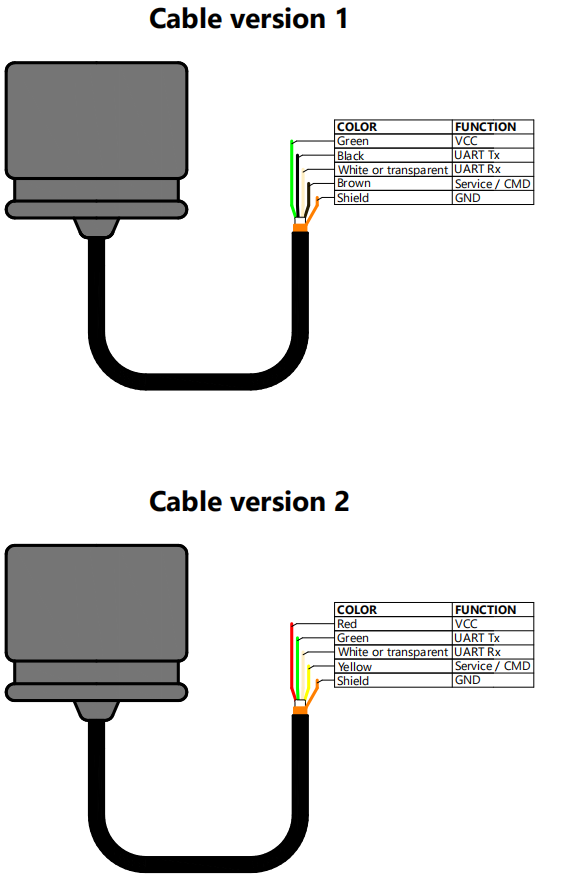
For an integrated version, you must use the USB-UART converter according to the pinout:
ATTENTION! The voltage of the data lines of the response beacon is 0 .. 3.3 V! Use only converters with suitable levels to connect beacons to a PC.
 |
|---|
| Functions of wires of Zima-R and Zima2-R responder beacons |
After connecting the beacon to the PC, launch the AzimuthSuite application and establish a connection by pressing the 🔌 LINK button (or the key combination Ctrl + L).
The application will search for the port, the progress and result of the search is displayed in the status bar.
After the connection is successfully established, the menu item 🛠 UTILS ⯈ 🤖 DEVICE ⯈ Responder settings… will become available. In the address setting dialog box that opens, the following functions are available:
- determination of the current beacon address (button 📤 QUERY)
- setting the specified beacon address (button 📥 APPLY)
Writing new settings to the non-volatile memory of the responder beacon takes from 1.5 to 3 seconds.
2.2.2. Working with the system
At this stage it is assumed that:
- Underwater antenna connector reviwed and closed (extension cable connected to DF antenna)
- The antenna is properly fixed to the pole and the extension cable has no loose slack
- The topside connector of the extension cable is connected to the power and switching unit, and the unit itself is turned off
- Power and switching unit connected to PC with USB-B cable
- If a dual-channel power supply and switching is used:
- External GNSS compass connected to the power supply and switching unit
- The offset of the direction finding antenna relative to the geolocation point (the position of the GNSS receiver) is measured and entered in the application settings
- Angle between compass and DF antenna zero measured and entered in app settings
- The second channel of the power supply and switching unit is connected to the PC using a USB-B cable
- All responder beacons with which work is supposed to have different addresses
- Addresses of all responder beacons with which work is supposed to be specified in the application settings
- If autonomous beacons are used, then the connectors connecting them to the battery packs are reviwed and tightly closed, the battery packs are fully charged
- If integrated beacons are used, then the cable connections with the carrier are reviwed for tightness (according to the type of connection)
- AzimuthSuite app launched
Beacons are recommended to be turned on in the surface position: within five seconds after power-up, atmospheric pressure is calibrated, which allows you to measure depth with greater absolute accuracy.
Since autonomous beacons turn on when the battery pack is immersed in water, it is recommended that the battery pack be immersed in water first, and the transponder beacon itself only after five seconds have passed.
It is desirable to turn on beacons in an integrated version before diving, if this is possible under current conditions.
To start the system, connect by pressing the 🔌 LINK button (or use the Ctrl + L key combination). The application will start searching for the connection port for the DF antenna and, if the corresponding setting is set, for the connection port for the external GNSS compass.
Then turn on the Bat&Link Box power and switching unit.
The connection status is displayed in the status bar at the bottom of the main application window. A green background below the corresponding text field indicates a successful connection.
It should be remembered that the application is designed to work with only one system device at a time: if both the direction finding antenna and one of the beacons are connected to the PC, then it is highly likely that the beacon will be the first to be detected when searching for the port. The search for the port of the direction finding station will not be performed in this case.
After the corresponding port (or ports) are detected, the system immediately proceeds to polling responder beacons, the addresses of which are specified in the settings. The work takes place in a fully automatic mode.
Make sure that the additional information text field is displayed (button 👽 on the map tools field is pressed) in the upper left corner of the map field. Immediately after connecting, the local parameters are displayed in the additional information field:
- depth, temperature, roll and pitch according to the readings of the built-in DF antenna sensor
- geographic position, speed, heading and azimuth angle if an external GNSS compass is connected.
The map field is arranged as follows: the position of the vessel (DF antenna) is displayed in the middle. If an external GNSS receiver is not used, then the null direction of the antenna is assumed to point to the top of the screen. If an external GNSS compass is connected, the heading to the top of the screen is the same as Geographic North, and the vessel is displayed based on the current heading angle.
The position of the responder beacons is displayed in the form of circles with numbers, the circles are connected by lines with the center of the polar coordinate system - the position of the direction-finding antenna or the geolocation point, if an external GNSS compass is used.
The list of responder beacons REMOTES (to the right of the map field) displays the parameters of responder beacons known to the system. When a responder beacon response is missed (or if the responder beacon did not receive the interrogation signal), the string TMO: ⚑ is displayed in the parameter list of this responder beacon.
If an external GNSS receiver is used, the system calculates their absolute geographic coordinates and the application accumulates tracks of their own position and the calculated positions of the transponder beacons. Tracks are not saved automatically! To save tracks, use the menu item 🛠 UTILS ⯈ 🗺 TRACKS ⯈ 💾 Export… (or the key combination Ctrl + S).
Saving in Google KML and CSV format is available.
The application allows you to emulate a GNSS receiver for one of the beacons in real time (if an external GNSS compass is used): the calculated coordinates can be transmitted as standard RMC and GGA messages via the serial port. The selection of the beacon address and the port name for emulation can be done while the system is running.
You should be aware of the factors that reduce the efficiency of the system, in particular:
- insufficient depth of the DF antenna
- location in the immediate vicinity of massive low-absorbing infrastructure facilities and ships
- lack of direct visibility through the water column between the direction-finding antenna and responder beacons
- high noise (both electromagnetic interference, for example, in the ship’s power supply network, and acoustic - a running engine of a ship or carrier, surf, other hydroacoustic systems, for example - sonars, etc.)
- the shallow depth of the reservoir and small reservoirs in general create difficult hydrological conditions for the operation of hydroacoustic navigation and communication systems
- shielding of the direction-finding antenna and responder beacon antennas
- impact on antennas of turbulent jets from propellers and/or wake
- water density stratification (thermocline, etc.)
2.3. Upon completion of work
- Turn off the power supply of the power supply and switching
- Disconnect all connectors on the panel of the power supply and switching
- Close all connectors with transport plugs
- In the presence of dirt or after working in salt water, flush all immersed parts of the equipment in fresh water
- Remove the DF antenna from the boom
- When storing for a long time (more than a week) or for transportation, open the underwater connector
- Before being placed in the shipping container, all moisture must be removed by natural drying without exposure to direct sunlight.
- For transponder beacons in an integrated design, if it is impossible to remove them from the carrier, it is mandatory to rinse in fresh water and remove any contaminants
3. Liability and Disclaimer
3.1. Terms of replacement and free warranty service
The manufacturer’s warranty covers only factory defects that appear during the operation of the device in accordance with this manual during the warranty period (2 years from the date of purchase).
The manufacturer guarantees free repair or replacement of faulty equipment from the delivery set that has failed due to a manufacturing defect.
The reasons for refusing free warranty service, free repair and replacement include:
- any mechanical damage of the equipment from the delivery set, incl. violation of the insulation of wires and cables;
- any damage caused by exposure to moisture and dirt due to improper use of the equipment supplied;
- any electrical damage caused by use of incomplete accessories (chargers); Incomplete does not include accessories supplied by the manufacturer or its representative to replace defective or lost ones;
- any traces of self-repair and/or opening of the equipment supplied.
3.2. Disclamer
ANY OF THE PARTS OF THE SUPPLY KIT, INDIVIDUALLY AND AS A PART OF THE SYSTEM, HEREINHERALL Referred to as the “SUPPLIED EQUIPMENT”:
- WAS NOT DESIGNED AS MEANS OF RESCUE
- NOT TESTED AS AS MEANS OF RESCUE
- ARE NOT MEANS OF RESCUE
- THE MANUFACTURER DECLARES THAT THE SUPPLIED EQUIPMENT IS SAFE WHEN USE ACCORDING TO THESE INSTRUCTIONS AND IS NOT RESPONSIBLE FOR ANY CONSEQUENCES OF THE SUPPLIED EQUIPMENT USE
THE MANUFACTURER GUARANTEE THAT THE ZIMA2 HYDRO-ACOUSTIC SYSTEM (hereinafter referred to as the SYSTEM):
- DESIGNED ONLY TO WORK WITH RESPONDER BEACONS DESIGNED TO WORK WITH THE SYSTEM
- STRUCTURALLY CANNOT BE USED FOR TRACKING OBJECTS NOT EQUIPPED WITH RESPONDER BEACONS DESIGNED FOR OPERATION WITH THE SYSTEM
- DOES NOT CONTAIN RADIO COMMUNICATIONS, RECORDING AND LONG-TERM STORAGE OF AUDIO SIGNALS
THE ABOVE LIMITATIONS CANNOT BE REMOVED BY ANY MANIPULATION WITH THE SETTINGS AND/OR CONTROLS OF THE SYSTEM DEVICES AND/OR THE SOFTWARE INTENDED TO WORK WITH THE SYSTEM