docs.unavlab.com
Main ❯ Navigation & tracking systems ❯ Bat & Link Box: User’s manual
 |
|
|---|---|
| www.unavlab.com support@unavlab.com |
Bat & Link Box - Autonomous power supply and interface converter User’s manual |
Bat & Link Box
User’s manual
Contents
- 1. Introducation
- 2. Appearance and controls
- 3. Connector pinouts
- 4. Working with the device
- 5. Storage and maintenance
- 6. Liability and Disclaimer
1. Introduction
The device Bat & Link Box combines the functions of an autonomous power source for the direction finding station Zima2-B (and older version - Zima-B) and a switching hub for interfacing the station with the user’s PC, as well as for connecting data sources about the heading and position of the direction finding station. Contains protection circuits against polarity reversal and overvoltage of connected devices.
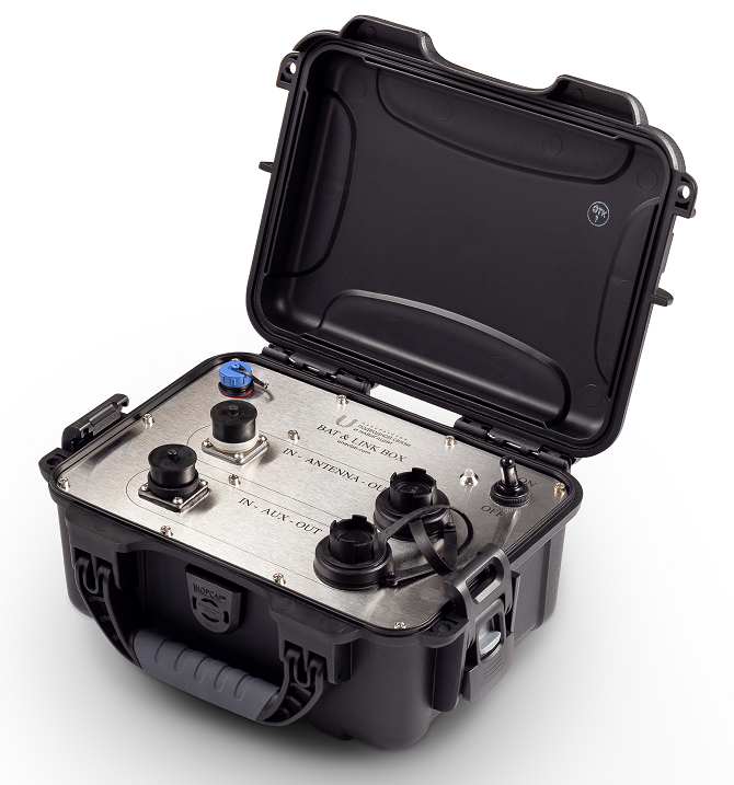
The device is housed in a small impact-resistant plastic case. Has the front panel from high-quality stainless steel. The modern lithium-iron phosphate batteries used in the device provide operation at negative temperatures and more than 3000 charge-discharge cycles. If necessary, it is possible to work from an AC source via complect AC adaptor.
2. Appearance and controls
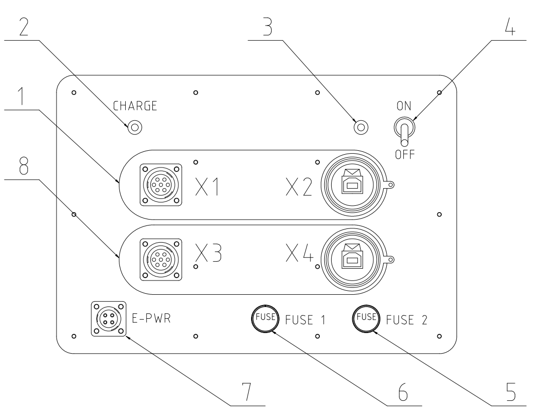
The appearance of the front panel of the device is shown in Figure 1. In the center of the panel there are connectors for connecting devices that support communication via the RS-422/485 interface and USB-B connectors. Connectors are grouped as 1 and 81. External devices are connected to connectors X1 and X3, these connectors provide power to connected external devices. The USB-B connectors X2 and X4 are intended for connection to the USB port of a PC.
 |
|---|
| Fig. 1 - Control panel |
| 1 - Line 1, 2 - Charge indicator, 3 - Power state indicator, 4 - power switch, 5 - battery line fuse2, 6 - external power line fuse2, 7 - Charger (AC/DC adaptor) connector2, 8 - line 2 |
Indicator 2 is on when the built-in power supply is being charged and off when it is not being charged. The two-color indicator 3 is used to show the power status of the system. Table 1 lists all options for possible light signals. Toggle switch 4 is designed to turn on the power of the device.
Fuses 5 and 6 protect the built-in battery and external power circuits, respectively. Fuses of size 5.2x20 with a nominal value of 5A are used.
Connector 7 is intended for connecting a network adapter, through which the built-in power supply is charged and the device is powered from the AC mains.
Table 1 - Indicator 3 states
| № | Indicator state | Description | Action to be taken |
|---|---|---|---|
| 1 | Green on | OK | |
| 2 | Green blinking | Built-in battery low | Charge the battery |
| 3 | Red on | Output short circuit | Shutdown the device, check connected consuming devices, cables, connectors |
| 4 | Red blinking | External power circuit error | Shutdown the device, check the AC/DC adaptor, cables, connectors |
1 Group 8 is present only in the extended version. The standard version contains only group 1.
2 On devices manufactured before July 2020, the fuse and external power supply connectors may be located on the side and/or back of the device case.
3. Connector pinouts
Table 2 - Connector pins 7 for connecting a network adapter
| № | Pin number | Function |
|---|---|---|
| 1 | 1, 3 | +U CHARGE |
| 2 | 2 | GND CHARGE |
| 3 | 4 | RESERVED |
Table 3 - Connector pins X1 (Group 1)
| Pin number | Function |
|---|---|
| 1 | +U |
| 2 | GND |
| 3 | Tx+ |
| 4 | NC |
| 5 | Tx- |
| 6 | Rx+ |
| 7 | Rx- |
Table 4 - Connector pins X3 (Group 8)
| Pin number | Function |
|---|---|
| 1 | +U |
| 2 | GND |
| 3 | Tx+ |
| 4 | NC |
| 5 | Tx- |
| 6 | Rx+ |
| 7 | Rx- |
4. Working with the device
Before use, the device must be placed on a stable horizontal base. When working on ships and moving objects, it is recommended to fix the device by the handle of the case with a cord.
Connecting and disconnecting connectors is recommended to be done when the toggle switch 4 is in the OFF position.
After the connection is completed and the toggle switch 4 is turned to the ON position. The status of the device is displayed using the indicator 3 in accordance with table 1.
5. Storage and maintenance
- Storage of the device is allowed only in the off state (toggle switch 4 to the OFF position), with the case lid closed and the connectors closed;
- During long-term (more than a month) storage, it is recommended to periodically check the condition of the built-in battery and, if necessary, charge it to prevent degradation of the built-in battery;
- Contaminants from the body of the device (case) can be removed with the lid closed using household soap solutions, followed by their thorough removal;
- Dirt on the front panel can be removed with a damp cloth, avoiding moisture and dirt getting into the connectors and fuse sockets;
- It is not allowed to use third-party chargers;
6. Liability and Disclaimer
6.1 Terms of replacement and free warranty service
The manufacturer’s warranty covers only factory defects that appear during the operation of the device in accordance with this manual during the warranty period (2 years from the date of purchase).
The manufacturer guarantees free repair or replacement of faulty equipment from the delivery set that has failed due to a manufacturing defect.
Reasons for refusing free warranty service, free repair and replacement include:
- any mechanical damage of the equipment from the delivery set, incl. violation of the insulation of wires and cables;
- any damage caused by exposure to moisture and dirt due to improper use of the equipment supplied;
- any electrical damage caused by use of incomplete accessories; Incomplete accessories do not include accessories supplied by the manufacturer or its representative in exchange for faulty or lost ones;
- any traces of self-repair and/or opening of the equipment supplied.
6.2 Manufacturer Liability Limitation
ANY OF THE PARTS OF THE SUPPLY KIT, INDIVIDUALLY AND AS A PART OF THE SYSTEM, HEREINHERALL Referred to as the “SUPPLIED EQUIPMENT”:
- NOT DEVELOPED AS A MEANS OF RESCUE
- NOT TESTED AS A RESCUE EQUIPMENT
- IS NOT A RESCUE EQUIPMENT
- THE MANUFACTURER DECLARES THAT THE SUPPLIED EQUIPMENT IS SAFE WHEN USE ACCORDING TO THESE INSTRUCTIONS AND IS NOT RESPONSIBLE FOR ANY CONSEQUENCES OF THE USE OF THE SUPPLIED EQUIPMENT