docs.unavlab.com
Main ❯ Navigation & tracking systems ❯ uTrackDiver application: User’s manual
ℹ This document can be printed directly from your browser. For best results:
- select the range of pages to print, excluding the first and last
- in advanced settings, disable footers and headers
| www.unavlab.com support@unavlab.com |
uTrackDiver application User’s manual |
uTrackDiver
User’s manual
Contents
1. Introduction
The 🤿 uTrackDiver application is designed to track the position of divers equipped with wireless voice communication diving stations RedPhone-DX.
Download the necessary software in advance. No installation is required - just unzip the contents of the archive to a location convenient for you.
2. Application interface and functions
2.1. Application Settings
We suggest starting your acquaintance with the application with its settings. The figure below shows a general view of the settings window; it can be called up by clicking the ‘⚙ SETTINGS’ button on the main toolbar of the main application window.
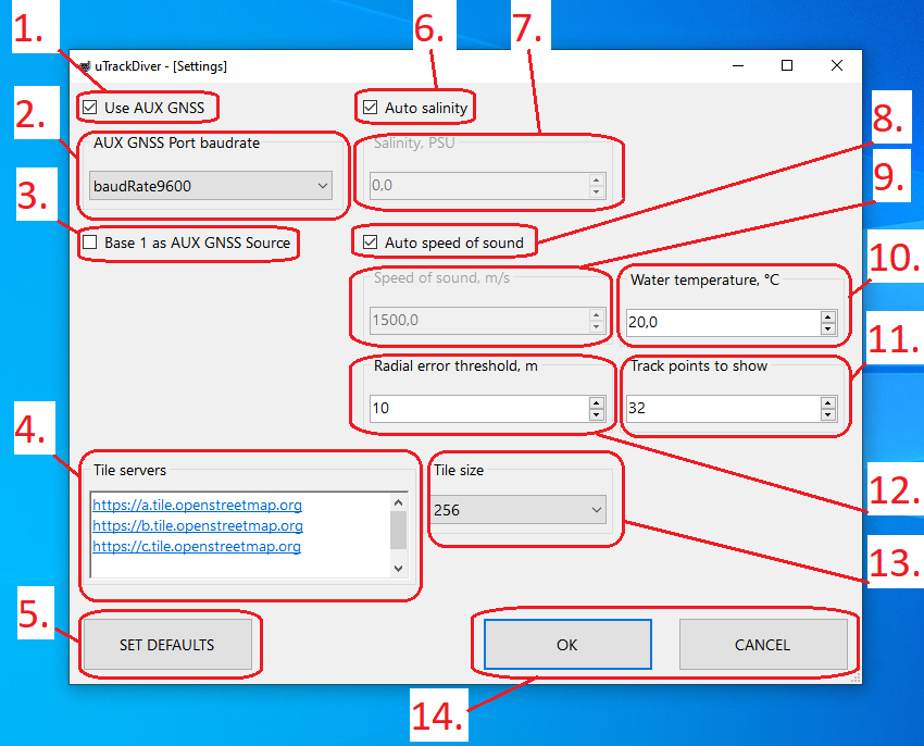 |
| Settings window controls |
| 1 - Indicator of using an additional source of navigation data (GNSS receiver), 2 - Drop-down list of port speed of an additional source of navigation data, 3 - Indicator of using the first buoy as an additional source of navigation data, 4 - List of servers-sources of map tiles, 5 - Button reset settings to default settings, 6 - Indicator for automatic selection of salinity (from the database), 7 - Input field for salinity, 8 - Indicator for auto-calculation of sound speed, 9 - Input field for sound speed, 10 - Input field for water temperature, 11 - Number of points track for display, 12 - Radial error threshold input field, 13 - Drop-down list for selecting the size of map tiles, 14 - Buttons for accepting settings and cancel |
The receiving radio modem is connected to the PC via a USB port. The application itself searches for a virtual serial port and does not require the user to specify any settings.
-
In some situations, it is convenient for the operator to see his own location on the map; this can be achieved in two ways: the first is to connect an additional GNSS receiver to the PC. In this case, the application needs to indicate that this method is used by checking the box 1 Use AUX GNSS. Also in this case, you need to specify the speed of the serial port at which the external GNSS receiver operates. The port itself does not need to be specified; the application will detect it itself.
-
If there is no external GNSS receiver, but the operator would like to see his own location on the map, you can use the second method: buoy No. 1 can be used as an external GNSS. This method has some limitations, for example, it is not always possible to position the operator next to the buoy; the buoys provide a limited set of navigation information compared to an external GNSS receiver. If this method is applicable to the current task, then you should check box 3 Base 1 as AUX GNSS Source. In this case, the checkbox in box 1 will be automatically unchecked.
-
The application allows you to display tracks on top of a map, the tiles of which can be downloaded via HTTPS. The Open Street Maps service is currently supported. Field 4 Tile servers indicates the server addresses, and field 13 Tile size indicates the size of the tiles in pixels. To download tiles, the application needs access to the Internet.
-
Button 5 SET DEFAULTS allows you to reset the settings to their default state.
-
Checkbox 6 Auto salinity means that the application will try to determine salinity from the database using the current geographic coordinates. The application contains a database of salinity of the surface of the world’s oceans in increments of 1 degree in latitude and longitude. Use this setting only in large bodies of water: seas and oceans. If you work in small inland reservoirs, it is recommended to uncheck 6 and set the appropriate water salinity value in field 7 Salinity, PSU. In most cases, for inland freshwater bodies, a value of 0 PSU is adequate. If you have accurate data on the salinity of the reservoir or it can be measured directly, you can also enter it in field 7. The salinity value is used to calculate the speed of sound.
-
Unchecking 7 Auto speed of sound and the corresponding field 9 Speed of sound, m/s allows you to set the application a known value for the speed of sound. If you have a direct measurement, otherwise it is recommended to set the checkbox to 7.
-
Field 10 Water temperature, °C allows you to specify the relevant water temperature value to the application. Water temperature is included in the calculation of the speed of sound if the 9 Auto speed of sound checkbox is checked. If you are measuring water temperature, it is recommended to take samples some distance from the surface.
-
Field 11 Track points to show tells the application how many points (calculated positions) for each track should be displayed simultaneously. This parameter affects display only. The application additionally stores all received points, which can then be saved.
-
Field 12 Radial error threshold, m indicates the radial error threshold (the value of the residual function at the end of solving the navigation problem), above which the calculated location is considered erroneous and discarded. It is recommended to set this value within 10 meters.
-
Buttons 14 OK and CANCEL are responsible for saving settings and canceling changes, respectively. After changing and saving the settings, the application will request a restart for the settings to take effect.
2.2. Main window
Let’s now look at the main application window. Its general view, indicating the main controls, is shown in the figure below.
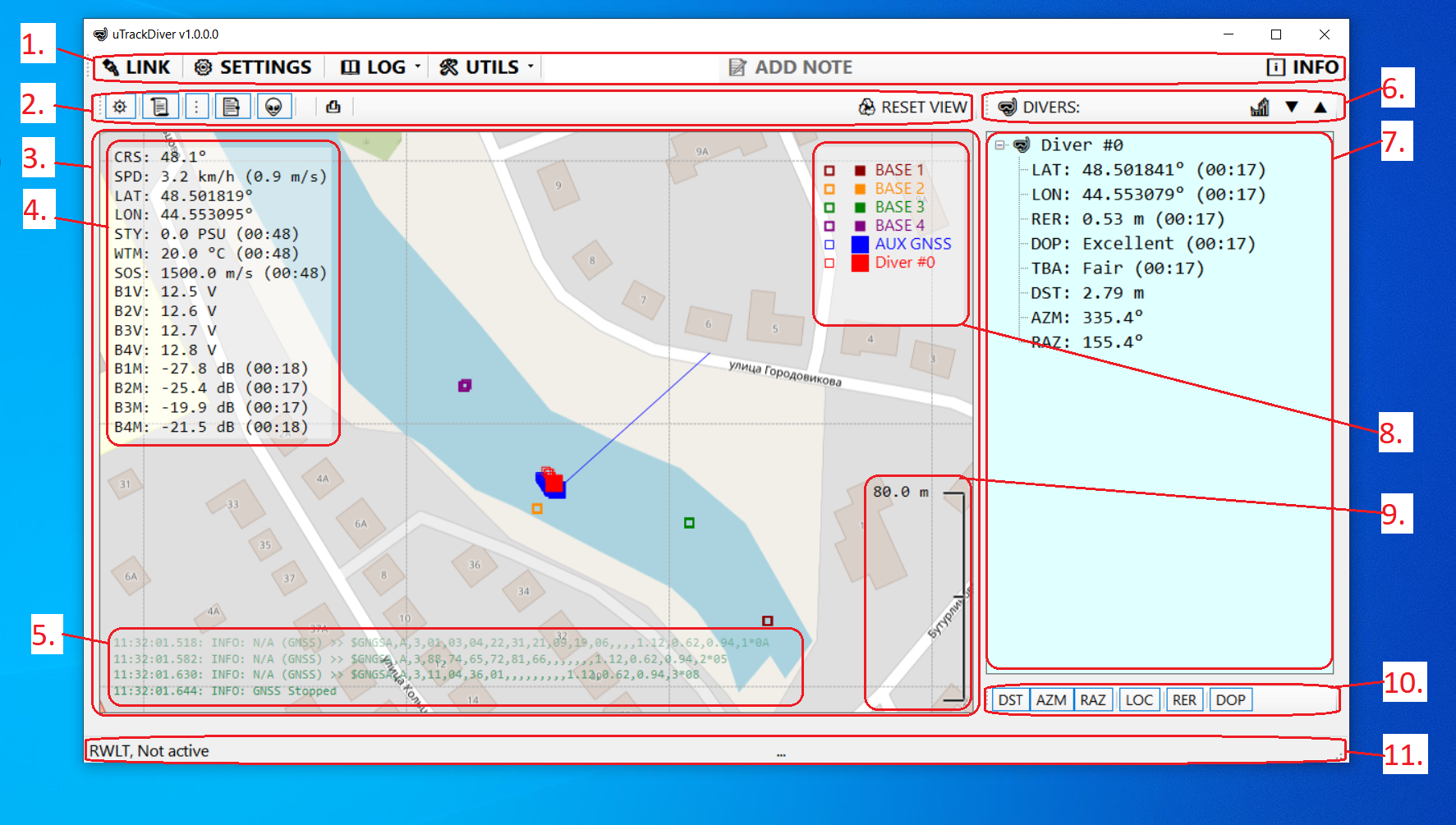 |
| Main elements of the main application window |
| 1 - Main toolbar, 2 - Map toolbar, 3 - Map field, 4 - Additional information field, 5 - Log field, 6 - Diver list toolbar, 7 - Diver list, 8 - Track designation field, 9 - Scale bar , 10 - Panel of switches for the displayed parameters of divers, 11 - Status line |
2.2.1. Main toolbar
- 1 - The main toolbar is located at the top of the window and contains the following elements:
- 🔌 LINK button - controls the connection to the receiving radio modem and external GNSS receiver.
- Button ⚙ SETTINGS - calls the settings editor. This button is not available when the connection is on or when playing a log file
- Menu 📖 LOG - contains functions for working with log files
- Item 👀 View current - open the current log file in the application associated with the ‘log’ extension (usually Notepad)
- Item ▶ Playback… - select a log file for playback in real time. This function allows you to almost completely restore the progress of work performed and, for example, restore a track that was not saved.
- Item 🧹Remove empty entries - clearing the LOG directory in the application folder: all log files smaller than 2 kilobytes in size and all empty folders will be deleted
- Item 🗜 Archive all entries… - packing the entire folder with log files into a Zip archive.
- Item 🗑 Clear all - deletes all application log files. Be careful! All files will be deleted without the possibility of recovery!!!
- Point 🧹+🗜+🗑 Do them all… - Deleting all empty folders, log files less than 2 kilobytes, packing the remaining log files into a Zip archive and deleting the originals in the LOG folder of the application.
- Menu 🛠 UTILS - contains additional functions
- Submenu 🗺 TRACKS - functions for working with tracks
- Item 💾 Export… - saving tracks in one of the supported formats through the system dialog
- Item 🗑 Clear - clearing tracks contained in the application memory
- Submenu 🗺 TRACKS - functions for working with tracks
- The input field and the 📝 ADD NOTE button are used to enter comments into the log file. You can simply type a text comment and press Enter regardless of which control has focus. Comments are saved with a timestamp, and in the future, when the log file is played back, the comments will be displayed at the corresponding point in time. This function allows you to quickly save any text notes about the progress of work.
- Button ℹ INFO - calls up a dialog with information about the application and links to additional information on the system.
2.2.2. Map Toolbar
- 2 - The map toolbar is located below the main toolbar on the left and contains the following elements:
- Button ⛯ - enable/disable display of base points (buoys). Sometimes it may be necessary to turn off the display of buoy positions on the map in order to zoom in and be able to view the divers’ movements in more detail. Changes in the state of this button are automatically saved and played back when playing log files.
- Button 📜 - enable/disable display of the log text field (5). Changes in the state of this button are automatically saved and played back when playing log files.
- Button ⋮ - enable/disable display of ‘legend’ - list of track designations (8). Changes in the state of this button are automatically saved and played back when playing log files.
- Button 📑 - enable/disable display of the comments field (NOTES). Changes in the state of this button are automatically saved and played back when playing log files.
- Button 👽 - enable/disable display of the additional information field (4). Changes in the state of this button are automatically saved and played back when playing log files.
- Button ⎙ - used to save a screenshot of the main application window. Screenshots are saved in the SCREENSHOTS directory in the application folder. The name of the last saved screenshot is displayed in the status bar (11).
- The ♻ RESET VIEW button allows you to reset the current view and displayed tracks.
- 3 - Map field - serves to display divers’ movement tracks, buoy positions on the base map, as well as:
- vertical scale bar (9)
- application log (5). This field displays the last 4 lines of the application log from bottom to top.
- legends (8). The legend matches the color and size of the dots and the name of the track.
- comments. To create comments about the progress of work on the fly, the operator simply needs to type them on the keyboard, and the typed text will be displayed in the input field on the main toolbar. By pressing the ‘Enter’ key, the text will be saved to the log and will be displayed on the right in the map field (if the corresponding switch ‘📑’ on the map toolbar is active).
- additional navigation information (4).
2.2.3. Map panel
- 3 - The map panel is designed to display the map, buoy locations, calculated diver positions and some additional information
2.2.4. Additional information field
- 4 - The additional information field is located in the upper left part of the map panel and serves to display additional information. The display of this field can be switched using the 👽 button on the map toolbar (2). Each parameter appears on a separate line, starting with a three-letter parameter identifier and a colon, followed by the parameter value and unit of measurement. The time in (MM:SS) format displayed next to the parameter shows how long ago the parameter value was updated. The table below provides a list of all possible identifiers and their descriptions:
| ID | Description | Units of measurement | Range |
|---|---|---|---|
| CRS | Course based on external GNSS data | ° | 0 .. 360 |
| SPD | Speed according to external GNSS | km/h (m/s) | >= 0 |
| LAT | Latitude according to external GNSS | ° | -90 .. 90 |
| LON | Longitude according to external GNSS data | ° | -180 .. 180 |
| STY | Salinity value (from settings or from database) | PSU | 0 .. 40 |
| WTM | Water temperature value (from settings) | °C | -10 .. +40 |
| SOS | Sound speed value (from settings or calculated) | m/s | 1300 .. 1600 |
| B1V | Voltage of the built-in battery of buoy No. 1 | V | 10 .. 13 |
| B2V | Voltage of the built-in battery of buoy No. 2 | V | 10 .. 13 |
| B3V | Voltage of the built-in battery of buoy No. 3 | V | 10 .. 13 |
| B4V | Voltage of the built-in battery of buoy No. 4 | V | 10 .. 13 |
| B1M | Signal level on buoy No. 1 | dB | 14 .. 36 |
| B2M | Signal level at buoy No. 2 | dB | 14 .. 36 |
| B3M | Signal level at buoy No. 3 | dB | 14 .. 36 |
| B4M | Signal level at buoy No. 4 | dB | 14 .. 36 |
2.2.5. Log field
- 5 - The log field is located at the bottom of the map panel and displays the last 4 lines of the application log. The visibility of this field is toggled with the 📜 button on the map toolbar (2).
2.2.6. Diver list toolbar
- 6 - The DIVERS diver list toolbar is located above the diver list on the left side of the main application window. The panel contains the following elements:
- Button 🎢 - sorting the list of divers by number.
- Button ▼ - collapse all list items.
- Button ▲ - expand all list elements.
2.2.7. List of divers
- 7 - The list of divers DIVERS is located on the left side of the main application window. The list has a tree structure, top-level nodes are in the format Diver #N, where N is the diver’s identifier, which is set in the settings of the diving communication station RedPhone-DX (setting up RWLT Diver’s ID, for more detailed information please refer to RedPhone-DX diving station operating instructions). Child nodes contain information about a given diver known to the system. Each individual parameter is represented by a line that begins with the parameter identifier, followed by the parameter value, separated by a colon. If the value of this parameter was updated more than 3 seconds ago, then the time elapsed since the parameter was updated in the format (MM:SS) is indicated in parentheses. Below is a list of possible parameters:
| ID | Description | Units of measurement | Range |
|---|---|---|---|
| LAT | Calculated latitude | ° | -90 .. 90 |
| LON | Calculated longitude | ° | -180 .. 180 |
| RER | Radial error | m | 0 .. 99 |
| DOP | Geometric factor reducing accuracy | - | - |
| TBA | The quality of the relative position of the positioned object and reference points | - | - |
| DST | Distance to diver from position according to external GNSS data | m | 0 .. 1500 |
| AZM | Direction (course) towards the diver from the position according to external GNSS data | ° | 0 .. 360 |
| RAZ | Reverse direction (course) from the diver to the position according to external GNSS data | ° | 0 .. 360 |
The most important parameters here are AZM, DST and RAZ: by azimuth and distance the operator can always understand where a particular diver is located relative to him, and he can report the RAZ parameter to the diver via voice communication, so that he, adhering to this course, can carry out the drive.
The display of various parameters is switched using the buttons on the panel (10). It should be understood that the parameters associated with the relative position of the diver and the surface point (range, forward and reverse course) can only be determined if there is an external source of navigation data - an external GNSS receiver that sets the system the location of the surface point for tracking divers or when the setting is turned on Base 1 as AUX GNSS - when all parameters are determined relative to buoy No. 1.
2.2.8. Legend field
- 8 - Legend field. Displayed in the upper right corner of the map field. It will display a list of tracks with example track points.
2.2.9. Scale bar
- 9 - The scale bar is displayed in the lower right corner of the map field and shows the map scale in meters.
2.2.10. Panel of switches for displayed diver parameters
- 10 - The panel of switches for the displayed parameters of divers is located below the list of divers and switches the visibility of parameters in the list:
- DST button - turns on/off the display of the distance to the diver. Changes in the state of this button are automatically saved and played back when playing log files.
- Button AZM - turns on/off the display of the direction to the diver. Changes in the state of this button are automatically saved and played back when playing log files.
- Button RAZ - turns on/off the display of the direction from the diver to the position according to the external GNSS receiver. Changes in the state of this button are automatically saved and played back when playing log files.
- LOC button - turns on/off the display of the diver’s location (latitude and longitude). Changes in the state of this button are automatically saved and played back when playing log files.
- Button RER - turns on/off the display of the radial error - the value of the residual function at which the solution to the problem of determining the location of the diver ended. Changes in the state of this button are automatically saved and played back when playing log files.
- DOP button - turns on/off the display of the DOP and TBA parameters.
2.2.11. Status line
- 11 - Status line. The line displays the status of the radio modem ports and the external source of navigation data (external GNSS receiver), the name of the last saved screenshot or Zip archive into which the log files were packed.