docs.unavlab.com
Main ❯ Underwater acoustic modems ❯ uWave: Communication protocol specification
ℹ Recommendations for printing / saving as PDF
- Press Ctrl+P (macOS: Cmd+P)
- Select "Save as PDF" (Microsoft Print to PDF) as the printer
- In "Pages", enter a range that excludes the first and the last page
- Disable headers and footers (title, URL, page numbers)
- In Chrome/Edge: More settings → "Margins" → None | in Firefox: "Margins & Header/Footer" → None
- Click Print and choose where to save the PDF
 |
|
|---|---|
| www.unavlab.com support@unavlab.com |
uWave - family of underwater acoustic communication devices Communication protocol specification |
uWave
Communication protocol specification
Contents
- 0. Version history & list of changes
- 1. Introduction
- 2. UWV command system for uWave underwater acoustic modems
- 2.1. IC_D2H_ACK - device response
- 2.2. IC_H2D_SETTINGS_WRITE - writing new settings
- 2.3. IC_H2D_RC_REQUEST - code request to a remote subscriber
- 2.4. IC_D2H_RC_RESPONSE - remote subscriber response
- 2.5. IC_D2H_RC_TIMEOUT - remote subscriber response timeout
- 2.6. IC_D2H_RC_ASYNC_IN - incoming code message from a remote subscriber
- 2.7. IC_H2D_AMB_DTA_CFG - configuring the output of ambient parameters
- 2.8. IC_H2D_AMB_DTA - ambient and power supply parameters
- 2.9. IC_H2D_DINFO_GET - request for device information
- 2.10. IC_D2H_DINFO - device information
- 2.11. IC_H2D_PT_SETTINGS_READ - read packet mode settings
- 2.12. IC_D2H_PT_SETTINGS - packet mode settings
- 2.13. IC_H2D_PT_SETTINGS_WRITE - write packet mode settings
- 2.14. IC_H2D_PT_SEND - send a message in packet mode
- 2.15. IC_D2H_PT_FAILED - message transmission in packet mode failed
- 2.16. IC_D2H_PT_DLVRD - message successfully transmitted in packet mode
- 2.17. IC_D2H_PT_RCVD - message received in packet mode
- 2.18. IC_H2D_PT_ITG - request to a remote subscriber with logical addressing
- 2.19. IC_D2H_PT_ITG_TMO - response timeout for a request with logical addressing
- 2.20. IC_D2H_PT_ITG_RESP - remote subscriber response with logical addressing
- 2.21. IC_H2D_INC_DTA_CFG - configuring the output of roll and pitch values
- 2.22. IC_D2H_INC_DTA - roll and pitch data
- 2.23. IC_H2D_AQPNG_SETTINGS_READ - request for AUTO QUERY / PINGER mode settings
- 2.24. IC_HDH_AQPNG_SETTINGS - AUTO QUERY / PINGER mode settings
- 3. Device operating modes
- 4. Identifiers
- 5. Appendices
- 5.1 Examples of working with the device in command mode
- 5.1.2 Example 1 - requesting device information
- 5.1.3 Example 2 - code request to a remote subscriber
- 5.1.4 Example 3 - setting up the output of ambient parameter data
- 5.1.5. Example 4 - Enabling packet mode
- 5.1.6. Example 5 - Transmission in packet mode and receiving a delivery notification
- 5.2. Recipes
0. Version history & list of changes
1. Introduction
1.1. Physical layer protocol
uWave underwater acoustic modems exchange data via the RS-232 physical layer standard for an asynchronous interface (UART) with a data line voltage of 3.3 V. The connection uses a four-wire cable with the wires Tx (transmitter), Rx (receiver), Vcc (power) and GND (ground). Without additional repeaters or interface converters, correct operation of the interface is guaranteed for a data bus length of up to 2 m.
Default connection port settings1:
Baudrate: 9600 bit/s
Data bits: 8
Stop bits: 1
Parity: No
Hardware flow control: No
CAUTION! The modems are powered by a DC source of 5–12 V, while the data line voltage is 3.3 V.
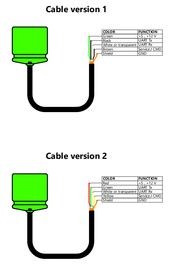 |
|---|
| Cable wire assignment of uWave modems |
1.2. NMEA0183 dialog layer protocol standard
The NMEA0183 standard describes the format of dialog layer text (ASCII) sentences.
Sentence example: $PUWV0,1,0*hh<CR><LF>
The main elements of an NMEA0183 sentence (message):
- ’$’ - sentence start,
- ‘P’ - Proprietary code
- ‘UVW’ - three-letter manufacturer identifier
- ‘0’ - sentence identifier
- ’,’ - comma (parameter delimiter)
- ‘*’ - checksum delimiter
- ‘hh’ - checksum in hexadecimal format (e.g. FF, 01). Calculated as the bitwise XOR of all bytes between ‘$’ and ‘*’.
- <CR><LF> - end of sentence (line break) ____ 1 The specified parameters can be changed on request
2. UWV command system for uWave underwater acoustic modems
The D2H prefix in a sentence name means that the sentence is sent from the Device to the Host (control system). The H2D prefix in a sentence name means that the sentence is sent from the Host (control system) to the Device.
2.1. IC_D2H_ACK
The IC_D2H_ACK sentence is the device’s response to a request received from the control system.
Sentence format: $PUWV0,x,x*hh<CR><LF>
| Field/Parameter | Description |
|---|---|
| $ | Sentence start ‘$’ |
| PUWV | UWV |
| 0 | Sentence ID |
| cmdID | ID of the command being processed (to which the device responded) |
| errCode | Error code (see 4.1) |
| * | NMEA checksum delimiter |
| hh | NMEA checksum |
| <CR><LF> | End of sentence |
2.2. IC_H2D_SETTINGS_WRITE
Writing new settings
Sentence format: $PUWV1,x,x,x.x,x,x,x.x*hh<CR><LF>
| Field/Parameter | Description |
|---|---|
| $ | Sentence start ‘$’ |
| PUWV | UWV |
| 1 | Sentence ID |
| txChID | Transmit channel ID |
| rxChID | Receive channel ID |
| STY | Salinity, PSU |
| isCmdMode | ‘0’ - command mode is controlled by the service pin, ‘1’ - command mode by default |
| isACKOnTXFinished | ‘1’ - the modem will send the IC_D2H_ACK sentence with the LOC_ACK_TX_FINISHED parameter when it has finished sending the message (when the acoustic transmitter buffer has been emptied), ‘0’ - the modem will not report that the transmission is finished |
| gravityAcc | Gravitational acceleration (for more accurate depth determination), in m/s2, in the range from 9.77 to 9.84 |
| * | NMEA checksum delimiter |
| hh | NMEA checksum |
| <CR><LF> | End of sentence |
2.3. IC_H2D_RC_REQUEST
Code request to a remote subscriber
Sentence format: $PUWV2,x,x,x*hh<CR><LF>
| Field/Parameter | Description |
|---|---|
| $ | Sentence start ‘$’ |
| PUWV | UWV |
| 2 | Sentence ID |
| txChID | Transmit channel ID |
| rxChID | Receive channel ID (in which the response is expected) |
| rcCmdID | Command ID (see 4.2) |
| * | NMEA checksum delimiter |
| hh | NMEA checksum |
| <CR><LF> | End of sentence |
2.4. IC_D2H_RC_RESPONSE
The remote subscriber’s response to a code request has been received
Sentence format: $PUWV3,x,x,x.x,x.x,x.x,x.x*hh<CR><LF>
| Field/Parameter | Description |
|---|---|
| $ | Sentence start ‘$’ |
| PUWV | UWV |
| 3 | Sentence ID |
| txChID | ID of the transmit channel in which the request was made |
| rcCmdID | Command ID (see 4.2) |
| propTime | Signal propagation time, s |
| MSR | Mean main lobe to side-peak ratio, dB |
| Value | Requested value |
| Azimuth | Horizontal angle of arrival of the signal (Only for uWave USBL devices, otherwise the field is empty) |
| * | NMEA checksum delimiter |
| hh | NMEA checksum |
| <CR><LF> | End of sentence |
2.5. IC_D2H_RC_TIMEOUT
The remote subscriber did not respond to the request
Sentence format: $PUWV4,x,x*hh<CR><LF>
| Field/Parameter | Description |
|---|---|
| $ | Sentence start ‘$’ |
| PUWV | UWV |
| 4 | Sentence ID |
| txChID | ID of the transmit channel in which the request was made |
| rcCmdID | Command ID (see 4.2) |
| * | NMEA checksum delimiter |
| hh | NMEA checksum |
| <CR><LF> | End of sentence |
2.6. IC_D2H_RC_ASYNC_IN
Incoming code message from a remote subscriber
Sentence format: $PUWV5,x,x.x,x.x*hh<CR><LF>
| Field/Parameter | Description |
|---|---|
| $ | Sentence start ‘$’ |
| PUWV | UWV |
| 5 | Sentence ID |
| rcCmdID | Command ID (see 4.2) |
| MSR | Mean main lobe to side-peak ratio, dB |
| Azimuth | Horizontal angle of arrival of the signal (Only for uWave USBL devices, otherwise the field is empty) |
| * | NMEA checksum delimiter |
| hh | NMEA checksum |
| <CR><LF> | End of sentence |
2.7. IC_H2D_AMB_DTA_CFG
Configuring the output of ambient and power supply parameters. This sentence configures the modem’s output of the readings of the built-in pressure/temperature sensor and of the supply voltage. After configuration, the modem can transmit these readings using the sentence IC_D2H_AMB_DTA
Sentence format: $PUWV6,x,x,x,x,x,x*hh<CR><LF>
| Field/Parameter | Description |
|---|---|
| $ | Sentence start ‘$’ |
| PUWV | UWV |
| 6 | Sentence ID |
| IsSaveToFlash | 1 - save the settings to Flash, 0 - do not save |
| PeriodMs | Information output period in milliseconds, 0 - readings output disabled, 1 - tandem output (immediately after any outgoing sentence from the device to the control system) or a value from 500 to 60000 (0.5–60 seconds) |
| IsPressure | 1 - output the pressure sensor readings, 0 - do not output |
| IsTemperature | 1 - output the temperature sensor readings, 0 - do not output |
| IsDepth | 1 - output the depth, 0 - do not output |
| IsVCC | 1 - output the supply voltage, 0 - do not output |
| * | NMEA checksum delimiter |
| hh | NMEA checksum |
| <CR><LF> | End of sentence |
If the PeriodMs parameter is zero but at least one of the flags IsPressure/IsTemperature/IsDepth/IsVCC is set, the device will transmit the specified parameters once.
2.8. IC_H2D_AMB_DTA
Ambient and power supply parameters.
Sentence format: $PUWV7,x.x,x.x,x.x,x.x*hh<CR><LF>
| Field/Parameter | Description |
|---|---|
| $ | Sentence start ‘$’ |
| PUWV | UWV |
| 7 | Sentence ID |
| Pressure_mBar | pressure in mbar |
| Temperature_C | temperature in °C |
| Depth_m | Depth in meters |
| VCC_V | Supply voltage in volts |
| * | NMEA checksum delimiter |
| hh | NMEA checksum |
| <CR><LF> | End of sentence |
2.9. IC_H2D_DINFO_GET
Request information about the device. The device responds to this sentence with the sentence IC_D2H_DINFO.
Sentence format: $PUWV?,x*hh<CR><LF>
| Field/Parameter | Description |
|---|---|
| $ | Sentence start ‘$’ |
| PUWV | UWV |
| ? | Sentence ID |
| Reserved | Reserved |
| * | NMEA checksum delimiter |
| hh | NMEA checksum |
| <CR><LF> | End of sentence |
2.10. IC_D2H_DINFO
Device information
Sentence format: $PUWV!,c--c,c--c,x,c--c,x,x.x,x,x,x,x.x,x,x*hh<CR><LF>
| Field/Parameter | Description |
|---|---|
| $ | Sentence start ‘$’ |
| PUWV | UWV |
| ! | Sentence ID |
| Serial number | Device serial number |
| System moniker | System name |
| System version | Version |
| Core moniker | Communication subsystem |
| Core version | Communication subsystem version |
| acBaudrate | Data rate, baud |
| rxChID | Receive channel ID |
| txChID | Transmit channel ID |
| maxChannels | Total number of available channel IDs |
| styPSU | Salinity, PSU (set by the user) |
| isPTS | ‘1’ - the device has a built-in pressure/temperature sensor, ‘0’ - it does not |
| isCmdMode | ‘1’ - command mode by default, ‘0’ - command mode is controlled via the service wire. |
| * | NMEA checksum delimiter |
| hh | NMEA checksum |
| <CR><LF> | End of sentence |
2.11. IC_H2D_PT_SETTINGS_READ
Read the packet mode settings. The device responds to this request with the sentence IC_D2H_PT_SETTINGS.
Sentence format: $PUWVD,x*hh<CR><LF>
| Field/Parameter | Description |
|---|---|
| $ | Sentence start ‘$’ |
| PUWV | UWV |
| D | Sentence ID |
| reserved | The field must contain ‘0’ |
| * | NMEA checksum delimiter |
| hh | NMEA checksum |
| <CR><LF> | End of sentence |
2.12. IC_D2H_PT_SETTINGS
Packet mode settings.
Sentence format: $PUWVE,x,x*hh<CR><LF>
| Field/Parameter | Description |
|---|---|
| $ | Sentence start ‘$’ |
| PUWV | UWV |
| E | Sentence ID |
| isPTMode | ‘0’ - packet mode is inactive, ‘1’ - packet mode is active. Not used since firmware version 1.20 - for transmission in packet mode it is sufficient for the modem to be in command mode, and a packet message can be received regardless of the mode the modem is in |
| ptLocalAddress | Address of the local modem in packet mode, 0 .. 254 |
| * | NMEA checksum delimiter |
| hh | NMEA checksum |
| <CR><LF> | End of sentence |
2.13. IC_H2D_PT_SETTINGS_WRITE
Packet mode settings. The device responds to this request with the sentence IC_D2H_PT_SETTINGS.
Sentence format: $PUWVF,x,x,x*hh<CR><LF>
| Field/Parameter | Description |
|---|---|
| $ | Sentence start ‘$’ |
| PUWV | UWV |
| F | Sentence ID |
| isSaveInFlash | ‘0’ - do not save the settings to flash, ‘1’ - save the settings to flash |
| isPTMode | ‘0’ - packet mode is inactive, ‘1’ - packet mode is active. Not used since firmware version 1.20 - for transmission in packet mode it is sufficient for the modem to be in command mode, and a packet message can be received regardless of the mode the modem is in |
| ptLocalAddress | Address of the local modem in packet mode 0 .. 254 |
| * | NMEA checksum delimiter |
| hh | NMEA checksum |
| <CR><LF> | End of sentence |
2.14. IC_H2D_PT_SEND
Send a data packet.
Sentence format: $PUWVG,x,x,h--h*hh<CR><LF>
| Field/Parameter | Description |
|---|---|
| $ | Sentence start ‘$’ |
| PUWV | UWV |
| G | Sentence ID |
| target_ptAddress | Address of the remote modem, 0 .. 254, 255 - broadcast message without receipt notification |
| maxTries | Maximum number of attempts, 0 .. 255. If the field is empty, the default maximum number of attempts, 255, will be used |
| dataPacket | An array of bytes in HEX format with the ‘0x’ prefix, for example, 0x313233 for the string ‘123’. The maximum packet size is 64 bytes. If the field is empty, the current transmission will be canceled. |
| * | NMEA checksum delimiter |
| hh | NMEA checksum |
| <CR><LF> | End of sentence |
2.15. IC_D2H_PT_FAILED
Data packet transmission was unsuccessful.
Sentence format: $PUWVH,x,x,h--h*hh<CR><LF>
| Field/Parameter | Description |
|---|---|
| $ | Sentence start ‘$’ |
| PUWV | UWV |
| H | Sentence ID |
| target_ptAddress | Address of the remote modem, 0 .. 254 |
| maxTries | Number of attempts made |
| dataPacket | An array of bytes in HEX format with the ‘0x’ prefix, for example, 0x313233 for the string ‘123’. The maximum packet size is 64 bytes. |
| * | NMEA checksum delimiter |
| hh | NMEA checksum |
| <CR><LF> | End of sentence |
2.16. IC_D2H_PT_DLVRD
The data packet has been successfully transmitted.
Sentence format: $PUWVI,x,x,x.x,h--h*hh<CR><LF>
| Field/Parameter | Description |
|---|---|
| $ | Sentence start ‘$’ |
| PUWV | UWV |
| I | Sentence ID |
| target_ptAddress | Address of the remote modem, 0 .. 254 |
| maxTries | Number of attempts made |
| azimuth | Horizontal angle of arrival of the signal, only for uWave USBL devices, otherwise the field is empty |
| dataPacket | An array of bytes in HEX format with the ‘0x’ prefix, for example, 0x313233 for the string ‘123’. The maximum packet size is 64 bytes. |
| * | NMEA checksum delimiter |
| hh | NMEA checksum |
| <CR><LF> | End of sentence |
2.17. IC_D2H_PT_RCVD
Data packet received.
Sentence format: $PUWVJ,x,x.x,h--h*hh<CR><LF>
| Field/Parameter | Description |
|---|---|
| $ | Sentence start ‘$’ |
| PUWV | UWV |
| J | Sentence ID |
| sender_ptAddress | Address of the remote modem (sender), 0 .. 254 |
| azimuth | Horizontal angle of arrival of the signal, only for uWave USBL devices, otherwise the field is empty |
| dataPacket | An array of bytes in HEX format with the ‘0x’ prefix, for example, 0x313233 for the string ‘123’. The maximum packet size is 64 bytes. |
| * | NMEA checksum delimiter |
| hh | NMEA checksum |
| <CR><LF> | End of sentence |
2.18. IC_H2D_PT_ITG
Request to a remote subscriber with logical addressing.
Sentence format: $PUWVK,x,x*hh<CR><LF>
| Field/Parameter | Description |
|---|---|
| $ | Sentence start ‘$’ |
| PUWV | UWV |
| K | Sentence ID |
| target_ptAddress | Address of the remote modem, 0 .. 254 |
| dataID | ID of the requested parameter (0 - depth, 1 - temperature, 2 - supply voltage) |
| * | NMEA checksum delimiter |
| hh | NMEA checksum |
| <CR><LF> | End of sentence |
2.19. IC_D2H_PT_ITG_TMO
Response timeout for a request with logical addressing.
Sentence format: $PUWVL,x,x*hh<CR><LF>
| Field/Parameter | Description |
|---|---|
| $ | Sentence start ‘$’ |
| PUWV | UWV |
| L | Sentence ID |
| target_ptAddress | Address of the remote modem, 0 .. 254 |
| dataID | ID of the requested parameter (0 - depth, 1 - temperature, 2 - supply voltage) |
| * | NMEA checksum delimiter |
| hh | NMEA checksum |
| <CR><LF> | End of sentence |
2.20. IC_D2H_PT_ITG_RESP
Remote subscriber response with logical addressing.
Sentence format: $PUWVM,x,x,x.x,x.x,x.x*hh<CR><LF>
| Field/Parameter | Description |
|---|---|
| $ | Sentence start ‘$’ |
| PUWV | UWV |
| M | Sentence ID |
| target_ptAddress | Address of the remote modem, 0 .. 254 |
| dataID | ID of the requested parameter (0 - depth, 1 - temperature, 2 - supply voltage) |
| dataValue | Value of the requested parameter |
| pTime | Signal propagation time, s |
| azimuth | Horizontal angle of arrival of the signal, °. Only for uWave USBL devices, otherwise the field is empty |
| * | NMEA checksum delimiter |
| hh | NMEA checksum |
| <CR><LF> | End of sentence |
2.21. IC_H2D_INC_DTA_CFG
Only for uWave USBL devices Configuring the output of roll and pitch data.
Sentence format: $PUWV8,x,x*hh<CR><LF>
| Field/Parameter | Description |
|---|---|
| $ | Sentence start ‘$’ |
| PUWV | UWV |
| 8 | Sentence ID |
| IsSaveToFlash | 1 - save the settings to Flash, 0 - do not save |
| PeriodMs | Information output period in milliseconds, 0 - readings output disabled, 1 - tandem output (immediately after any outgoing sentence from the device to the control system) or a value from 500 to 60000 (0.5–60 seconds) |
| * | NMEA checksum delimiter |
| hh | NMEA checksum |
| <CR><LF> | End of sentence |
2.22. IC_D2H_INC_DTA
Only for uWave USBL devices Roll and pitch data.
Sentence format: $PUWV9,x.x,x.x,x.x*hh<CR><LF>
| Field/Parameter | Description |
|---|---|
| $ | Sentence start ‘$’ |
| PUWV | UWV |
| 9 | Sentence ID |
| reserved | The field is reserved and left empty |
| Pitch | Roll value in degrees |
| Roll | Pitch value in degrees |
| * | NMEA checksum delimiter |
| hh | NMEA checksum |
| <CR><LF> | End of sentence |
2.23. IC_H2D_AQPNG_SETTINGS_READ
Supported since version 1.30
Request for the AUTO QUERY / PINGER mode settings.
Sentence format: $PUWVN,x*hh<CR><LF>
| Field/Parameter | Description |
|---|---|
| $ | Sentence start ‘$’ |
| PUWV | UWV |
| N | Sentence ID |
| reserved | The field is reserved and left empty |
| * | NMEA checksum delimiter |
| hh | NMEA checksum |
| <CR><LF> | End of sentence |
2.24. IC_HDH_AQPNG_SETTINGS
Supported since version 1.30 Sentence used to configure the AUTO QUERY / PINGER mode. The device also uses this sentence to notify the user that the settings of this mode have been changed successfully.
The period setting applies only to the pinger mode. The receive and transmit code channel IDs are used only if IsPT = 0. PTTargetAddress is used only in master mode and if IsPT = 1.
Sentence format: $PUWVO,x,x,x,x,x,x,x,x*hh<CR><LF>
| Field/Parameter | Description |
|---|---|
| $ | Sentence start ‘$’ |
| PUWV | UWV |
| O | Sentence ID |
| IsSaveToFlash | 1 - save the settings to Flash, 0 - do not save |
| AQPNG_Mode | 0 - mode inactive, 1 - pinger, 2 - master (auto query) |
| PeriodMs | Period for the pinger mode in milliseconds, a value from 2000 to 300000 (2 seconds–5 minutes) |
| RcTxID | Transmit channel ID for command mode |
| RcRxID | Receive channel ID for command mode |
| DataID | 0 - depth, 1 - temperature, 2 - supply voltage, 3 - all three in a cycle |
| IsPT | 0 - operation in command mode, 1 - operation with packet requests |
| PTTargetAddress | Address of the target subscriber in packet mode (for Master mode) |
| * | NMEA checksum delimiter |
| hh | NMEA checksum |
| <CR><LF> | End of sentence |
3. Device operating modes
3.1. Transparent channel mode
In transparent channel mode, the devices do not analyze the data coming from the control system and transmit it unchanged into the underwater acoustic channel, where it can be received by any other uWave modem receiving in the same code channel in which the transmission was made, provided that packet transmission mode is not activated on the receiving modem.
3.2. Command mode
uWave modems provide the user with a so-called “transparent channel”, in which all data fed to the device input is transmitted unchanged and without analysis into the underwater acoustic channel, after which it is received by another modem and delivered to the user on the receiving side in unchanged form. For this reason, a command mode exists, so that the modems can be configured and the propagation time to remote subscribers can be measured. The modems analyze input data only in command mode. To enter command mode, the SVC/CMD wire must be pulled to +3.3 V. After that, to exit command mode, the “service” wire must be pulled to ground. Command mode can also be enabled by default using the sentence IC_H2D_SETTINGS_WRITE, with the parameter isCmdMode = 1; in this case, starting from firmware version 1.30, the SVC/CMD wire becomes a digital output line that goes to a high logic state synchronously with the start of signal emission by the modem and 500 ms after the start of an incoming message is detected. To return to control by the level on the service wire, the sentence IC_H2D_SETTINGS_WRITE with the parameter isCmdMode = 0 can also be used.
In command mode, the devices can transmit short code requests to other devices: request the depth, temperature and supply voltage of a remote modem and transmit 8 user commands. Code requests have fixed lengths of request and response signals, which allows the requesting system to determine the propagation time (and slant range) to the requested system. The remote modem receives and processes a code request regardless of the mode it is in, which relieves the user system of the need to monitor the state of the remote modem.
CAUTION! The SVC/CMD wire must be pulled ONLY to 3–5 V or to ground; connecting it to a higher voltage will cause IRREPARABLE damage to the device that is NOT COVERED BY THE WARRANTY.
CAUTION! Before powering on the device, the SVC/CMD wire must be pulled to ground, otherwise the device will enter the firmware update mode.
Below are the diagrams for enabling and disabling command mode using the SVC/CMD wire when the modem is connected to a PC via a UART-USB interface converter.
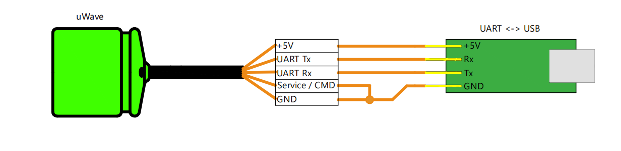 |
|---|
| Connecting the modem to a PC USB port using an interface converter. Command mode off |
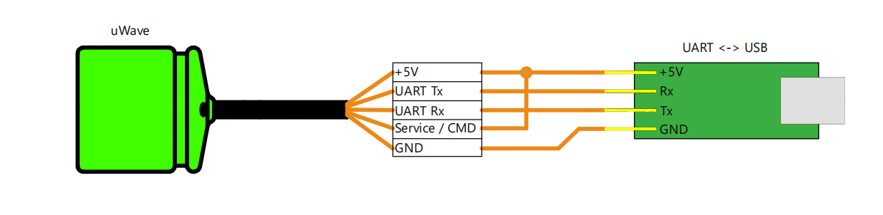 |
|---|
| Connecting the modem to a PC USB port using an interface converter. Command mode on |
3.3. Packet mode
Packet mode allows the user to transmit data in packets of up to 64 bytes with guaranteed delivery (ALO - at-least-once, it is guaranteed that the message will be transmitted at least 1 time) and receipt notification, as well as to request parameters with simultaneous measurement of the signal propagation time. Since the modem’s interaction with the user system in packet mode is implemented using sentences in the NMEA0183 format, both the transmitting and the receiving device must be switched to command mode to work in this mode. In packet mode, up to 255 devices can be addressed (addresses from 0 to 254, address 255 is assigned for transmitting broadcast messages without notification). The following functions are available to the user:
- setting the address of the local modem
- addressed transmission of a data packet to a remote device
- receiving a notification of successful packet delivery and the number of attempts required
- receiving a notification that the attempt interval has been exceeded in case of a failed transmission
- receiving an incoming packet message with the sender’s address
- requesting the parameters of a remote subscriber (depth, temperature, supply voltage) with propagation time measurement
- receiving a response timeout notification
- receiving the response of a remote subscriber with the requested parameter and the measured signal propagation time
To interact with the modem in packet mode, use the commands from 2.11. IC_H2D_PT_SETTINGS_READ to 2.17. IC_D2H_PT_RCVD.
After data are transmitted in packet mode, the sending modem waits for a short code message ACK from the addressee; upon receiving it, it notifies the user of the successful transmission, or it repeats the transmission until a response is received from the addressee or the number of attempts is exceeded.
4. Identifiers
4.1. Error codes
| Error | Value | Description |
|---|---|---|
| LOC_ERR_NO_ERROR | 0 | Request accepted |
| LOC_ERR_INVALID_SYNTAX | 1 | Syntax error |
| LOC_ERR_UNSUPPORTED | 2 | Request not supported |
| LOC_ERR_TRANSMITTER_BUSY | 3 | Transmitter is busy |
| LOC_ERR_ARGUMENT_OUT_OF_RANGE | 4 | Specified parameter is out of the valid range |
| LOC_ERR_INVALID_OPERATION | 5 | Invalid request |
| LOC_ERR_UNKNOWN_FIELD_ID | 6 | Unknown identifier |
| LOC_ERR_VALUE_UNAVAILIBLE | 7 | Requested parameter is not available at the moment |
| LOC_ERR_RECEIVER_BUSY | 8 | Receiver is busy (waiting for a response from the remote system) |
| LOC_ERR_TX_BUFFER_OVERRUN | 9 | Transmitter buffer is full |
| LOC_ERR_CHKSUM_ERROR | 10 | Checksum error |
| LOC_ACK_TX_FINISHED | 11 | The acoustic transmitter has finished transmitting the message |
| LOC_ACK_BEFORE_STANDBY | 12 | The device is entering STAND-BY mode |
| LOC_ACK_AFTER_WAKEUP | 13 | The device has exited STAND-BY mode |
| LOC_ERR_SVOLTAGE_TOO_HIGH | 14 | Supply voltage is too high (more than 13 volts) and the power amplifier will not be used to prevent it from failing |
4.2 Remote commands
| Command | Value | Description |
|---|---|---|
| RC_PING | 0 | Ping |
| RC_PONG | 1 | Pong |
| RC_DPT_GET | 2 | Request for the depth of the remote subscriber |
| RC_TMP_GET | 3 | Request for the temperature value of the remote subscriber |
| RC_BAT_V_GET | 4 | Request for the supply voltage of the remote subscriber |
| RC_ERR_NSUP | 5 | The remote system responded - request not supported |
| RC_ACK | 6 | The remote system responded - request accepted |
| RC_USR_CMD_000 | 7 | User command |
| RC_USR_CMD_001 | 8 | User command |
| RC_USR_CMD_002 | 9 | User command |
| RC_USR_CMD_003 | 10 | User command |
| RC_USR_CMD_004 | 11 | User command |
| RC_USR_CMD_005 | 12 | User command |
| RC_USR_CMD_006 | 13 | User command |
| RC_USR_CMD_007 | 14 | User command |
| RC_USR_CMD_008 | 15 | User command |
| RC_MSG_ASYNC_IN | 16 | Incoming message in transparent channel mode |
5. Appendices
5.1. Examples of working with the device in command mode
In the examples below, the prefix << precedes the commands sent to the device, and the prefix >> precedes the commands coming from
the device.
It is assumed that the device is connected to a control system and command mode is enabled.
5.1.2. Example 1 - requesting device information
<< $PUWV?,0*27<CR><LF>
PUWV? = IC_H2D_DINFO_GET
>> $PUWV!,3A001E000E51363437333330,STRONG,256,uWAVE [JULY],257,78.27,0,0,28,0.0,1,0*18<CR><LF>
PUWV! = IC_D2H_DINFO
3A001E000E51363437333330 = serial number,
STRONG = system name
256 = 0x0100 system version 01.00
uWAVE [JULY] = communication subsystem name,
257 = 0x0101 communication subsystem version 01.01
78.27 = data rate over the underwater acoustic channel, bit/s
0 = transmit channel ID
0 = receive channel ID
28 = total number of available code channels
0.0 = salinity, PSU
1 = the built-in pressure/temperature sensor is present and operational
0 = default command mode is disabled
5.1.3. Example 2 - code request to a remote subscriber
<< $PUWV2,0,0,2*28
PUWV2 = IC_H2D_RC_REQUEST
0 = Transmit channel ID (receive channel ID of the addressee)
0 = Receive channel ID (transmit channel ID of the addressee)
2 = Request ID = RC_DPT_GET
>> $PUWV0,2,0*36
PUWV0 = IC_D2H_ACK
2 = ACK for the PUWV2 request
0 = Error code = LOC_ERR_NO_ERROR
>> $PUWV3,0,2,0.00020,22.75,0.000,*1B
PUWV3 = IC_D2H_RC_RESPONSE
0 = receive channel ID of the remote subscriber
2 = Request ID = RC_DPT_GET
0.00020 = signal propagation time, s
22.75 = MSR (Main lobe to side-peak ratio), dB
0.000 = received value (in this case, the depth of the remote modem in meters)
<< $PUWV2,0,0,3*29
PUWV2 = IC_H2D_RC_REQUEST
0 = Transmit channel ID (receive channel ID of the addressee)
0 = Receive channel ID (transmit channel ID of the addressee)
3 = Request ID = RC_TMP_GET
>> $PUWV0,2,0*36
PUWV0 = IC_D2H_ACK
2 = ACK for the PUWV2 request
0 = Error code = LOC_ERR_NO_ERROR
>> $PUWV3,0,3,0.00030,26.31,27.300,*29
PUWV3 = IC_D2H_RC_RESPONSE
0 = receive channel ID of the remote subscriber
2 = Request ID = RC_TMP_GET
0.00030 = propagation time, s
26.31 = MSR (Main lobe to side-peak ratio), dB
27.300 = received value (in this case, the temperature of the remote subscriber in °C)
5.1.4. Example 3 - setting up the output of ambient parameter data
<< $PUWV6,0,1000,1,1,1,1*03<CR><LF>
PUWV6 = IC_H2D_AMB_DTA_CFG
0 = isSaveToFlash = false
1000 = transmit the data every 1000 ms
1 = isPressure = true
1 = isTemperature = true
1 = isDepth = true
1 = isVCC = true
>> $PUWV0,6,0*32<CR><LF>
PUWV0 = IC_D2H_ACK
6 = ACK for the PUWV6 request
0 = Error code = LOC_ERR_NO_ERROR
>> $PUWV7,1025.2,29.9,-0.014,5.0*18
. . .
>> $PUWV7,1026.3,29.9,-0.002,5.0*1D
PUWV7 = IC_D2H_AMB_DTA
1026.3 = pressure, mbar
29.9 = temperature, °C
-0.002 = depth, m
5.0 = supply voltage, V
<< $PUWV6,0,0,0,0,0,0*32
PUWV6 = IC_H2D_AMB_DTA_CFG
0 = isSaveToFlash = false
0 = do not transmit data
0 = isPressure = false
0 = isTemperature = false
0 = isDepth = false
0 = isVCC = false
>> $PUWV0,6,0*32
PUWV0 = IC_D2H_ACK
6 = ACK for the PUWV6 request
0 = Error code = LOC_ERR_NO_ERROR
5.1.5. Example 4 - Enabling packet mode
<< $PUWVF,1,1,0*5E<CR><LF>
PUWVF = IC_H2D_PT_SETTINGS_WRITE
1 = Save settings to flash = true
1 = Packet mode enabled = true
0 = Address of the local device = 0
>> $PUWVE,1,0*40
PUWVE = IC_D2H_PT_SETTINGS
1 = Packet mode enabled
0 = Address of the local device
5.1.6. Example 5 - Transmission in packet mode and receiving a delivery notification
<< $PUWVG,0,8,0x313233*2C
PUWVG = IC_H2D_PT_SEND
0 = Target address
8 = Maximum number of attempts
0x313233 = array of three bytes (‘123’)
>> $PUWV0,G,0*43
PUWV0 = IC_D2H_ACK
G = ACK for the PUWVG request
0 = Error code = LOC_ERR_NO_ERROR
$PUWVI,0,1,,0x313233*07
PUWVI = IC_D2H_PT_DLVRD
0 = addressee
1 = number of attempts made
empty field - the device does not support determination of the horizontal angle of arrival of the signal
0x313233 = array of three bytes (‘123’)
5.2. Recipes
It is assumed that the device is connected to a control system and command mode is enabled. The sentences can be copied and sent to the modem after appending the characters <CR><LF> (New line, Hex: 0x0D 0x0A, Dec: 13 10, or \r\n).
Recipe 1
Setting the basic settings to their default values
- Receive and transmit channel IDs - 0
- Default command mode disabled
- ACK on transmission completion disabled
- Salinity 0.0 PSU
- Gravitational acceleration 9.8067 m/s2
$PUWV1,0,0,0.,0,0,9.8067*35
Recipe 2
Disabling the automatic transmission of all ambient parameters and the supply voltage with the settings saved to flash.
$PUWV6,0,0,0,0,0,0*32
Recipe 3
Enabling the automatic transmission of all ambient parameters and the supply voltage 1 time per second without saving these settings to flash.
$PUWV6,0,1000,1,1,1,1*03
Recipe 4
Enabling the automatic transmission of all ambient parameters and the supply voltage after any outgoing sentence from the modem without saving the settings to flash.
$PUWV6,0,1,1,1,1,1*33
Recipe 5
Enabling the automatic transmission of only the depth of the local modem after any outgoing sentence from the modem without saving the settings to flash.
$PUWV6,0,1,0,0,1,0*32
Recipe 6
Request the depth of the remote modem with receive and transmit channel IDs of 0.
$PUWV2,0,0,2*28