docs.unavlab.com
Main ❯ Navigation & tracking systems ❯ AzimuthSuite: User’s manual
ℹ Recommendations for printing / saving as PDF
- Press Ctrl+P (macOS: Cmd+P)
- Select "Save as PDF" (Microsoft Print to PDF) as the printer
- In "Pages", enter a range that excludes the first and the last page
- Disable headers and footers (title, URL, page numbers)
- In Chrome/Edge: More settings → "Margins" → None | in Firefox: "Margins & Header/Footer" → None
- Click Print and choose where to save the PDF
 |
|
|---|---|
| www.unavlab.com support@unavlab.com |
AzimuthSuite - Application for the Zima2 USBL system User’s manual |
AzimuthSuite
User’s manual
Contents
1. AzimuthSuite application
ℹ Information
The AzimuthSuite application is no longer supported. It is recommended to use the console application AzimuthConsole. This section is retained for users who have not yet completed the transition to the new software.
1.1. Interface and functions
The host application 🐙 AzimuthSuite is designed to run on Windows 10 or later with .NET Framework 4.8 installed. The application is portable and does not require installation. Simply unpack the archive to a location convenient for the operator. The application and all the libraries it uses were developed by UCNL LLC and are open source.
The host application communicates with the system devices over a serial port according to the open NMEA-like protocol.
1.1.1. Application settings
The application uses two types of settings:
- basic system settings, which are stored in the
AzimuthSuite.settingsfile in the application directory. These settings are read by the application at startup and saved at the user’s command from the settings editor. - interface settings, which are stored in the
AzimuthSuite.uisettingsfile in the application directory. These settings are read by the application at startup and saved automatically when the application exits.
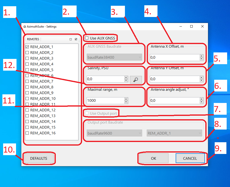
The application settings editor window is shown in the figure below.
 |
|---|
| Application settings editor |
| 1 - List of the responder-beacons in use, 2 - External GNSS compass usage option, 3 - External GNSS compass port baud rate, 4 - Offset of the antenna position from the GNSS compass position in the transverse direction, 5 - Offset of the antenna position from the GNSS compass position in the longitudinal direction, 6 - Angular correction (the angle between the zero direction of the GNSS compass and the zero direction of the antenna), 7 - Output port usage option, 8 - Output port baud rate, 9 - Accept and cancel buttons, 10 - Button to reset the settings to their default values, 11 - Maximum distance to the responder-beacons, 12 - Water salinity |
The system supports sequential operation with 16 responder-beacons. The operator can select the required beacon addresses in list 1 by checking the corresponding checkboxes. Always check only the boxes next to the addresses that will be used in the current job; otherwise the system will waste time polling beacons that are not present in the water area.
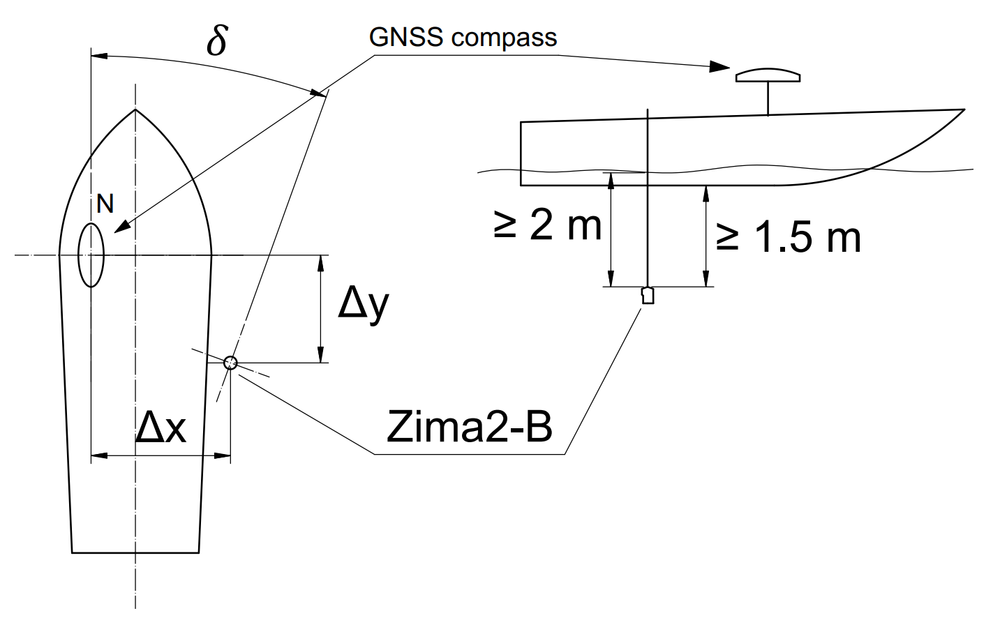
Connection of an external GNSS compass is supported via a serial port. To enable it, check box 2 and specify the port baud rate. The port itself will be detected by the system automatically. If the compass is not installed coaxially with the antenna (not on the pole), you will need to specify the position of the antenna relative to the position of the GNSS compass: the position of the GNSS compass is taken as the origin of a Cartesian coordinate system, and the transverse 4 and longitudinal 5 offsets of the antenna from this point are specified (transverse in the port-to-starboard direction, longitudinal in the stern-to-bow direction). If the zero directions of the compass and the antenna do not coincide, you must specify the angular correction 6 - the angle between the zero directions of the compass and the antenna, measured clockwise from the zero direction of the compass.
The position of the direction-finding antenna relative to the reference point is illustrated below:
 |
|---|
| Setting the position of the direction-finding antenna relative to the reference point and the zero direction of the compass |
| Offsets of the antenna relative to the GNSS compass: transverse ΔX and longitudinal ΔY; angular misalignment between the zero directions of the compass and the direction-finding antenna 𝛿 |
When working in sea water, specify the salinity using the controls of group 12: either enter a known value in the input field or use the built-in database of world ocean salinities by pressing the 🔎 button and specifying the current geographic coordinates.
When working in inland fresh water bodies, set the water salinity to 0.0 PSU. The salinity value is needed for the system to determine the depth and the speed of sound more accurately.
The maximum distance to the beacon is set in field 11 and determines the maximum time interval for waiting for the beacon’s response. The value is set in the range from 500 to 5999 m. Specify the minimum value applicable to the current operating conditions, since this value directly determines the speed of the system and its idle time when a response from the responder-beacon is missed.
If you need to transmit the calculated geographic position of one of the responder-beacons to another system as standard NMEA sentences (GGA, RMC), enable setting 7 and specify the name and baud rate of the port to which the application will output the data. Since the port is used only for transmission, it cannot be detected automatically, and its name must be specified.
When you press the OK button, the application will save the settings and prompt you to restart so that the new settings take effect.
1.1.2. Main application window
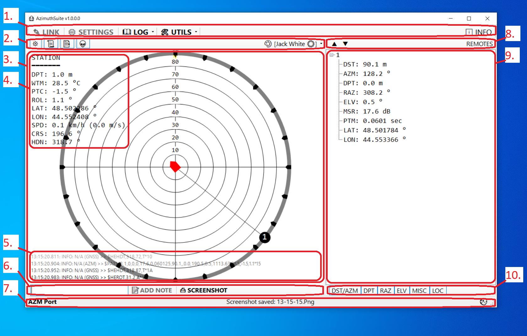
The main application window is shown in the figure below.
 |
|---|
| Main application window |
| 1 - Main toolbar, 2 - Map toolbar, 3 - Map field, 4 - Additional parameters text field, 5 - Log text field, 6 - Additional toolbar, 7 - Status line, 8 - Responder-beacon list toolbar, 9 - Responder-beacon list, 10 - Switch panel for the parameters displayed in the responder-beacon list |
- 1. Main toolbar is located at the top of the application window and contains the following elements:
- The 🔌 LINK button enables and disables communication with all devices. When the connection is enabled, the application will search for the connected Zima2-B direction-finding antenna and the external GNSS compass (if the setting is enabled). This function is also available via the
Ctrl + Lkey combination. - The ⚙ SETTINGS button opens the settings editor. It becomes unavailable while the connection is active and while a log file is being played back
- The 📖 LOG menu contains functions for working with log files
- The 👀 View current item opens the current log file in the application associated with the ‘log’ extension (usually Notepad). This function is also available via the
Ctrl + Hkey combination - The ▶ Playback… item lets you select a log file for playback in real time. This function allows you to reconstruct the course of the work almost completely and, for example, to recover a track that was not saved.
- The 🧹 Clear empty entries item cleans up the LOG directory in the application folder: all log files smaller than 2 kilobytes and all empty folders will be deleted
- The 🗜 Archive all entries… item packs the entire folder with the log files into a Zip archive.
- The 🗑 Delete all entries item deletes all application log files. Be careful! All files will be deleted permanently and cannot be recovered!!!
- The 🧹+🗜+🗑 Do them all… item deletes all empty folders and all log files smaller than 2 kilobytes, packs the remaining log files into a Zip archive and deletes the originals in the application’s LOG folder.
- The 👀 View current item opens the current log file in the application associated with the ‘log’ extension (usually Notepad). This function is also available via the
- The 🛠 UTILS menu
- The 🗺 TRACKS submenu contains functions for working with tracks
- The 💾 Export… item is used to save tracks in Google KML or CSV (comma-separated values) format. This function is available via the
Ctrl + Skey combination - The 🤖 DEVICE submenu
- The View info… item is available only while the connection is active and a device (a direction-finding antenna or a responder-beacon) is connected, and opens a window with information about the device: its type, firmware version and serial number
- The Responder settings… item is available only while the connection is active and a responder-beacon is connected. It opens the responder-beacon settings editor. The function is also available via the
Ctrl + Rkey combination
- The 💾 Export… item is used to save tracks in Google KML or CSV (comma-separated values) format. This function is available via the
- The 🗺 TRACKS submenu contains functions for working with tracks
- The group of elements for controlling the output port contains:
- The 🔄 button refreshes the list of available serial ports
- Drop-down list of the available ports for use as the output port
- Drop-down list of the addresses of the responder-beacons whose coordinates are to be transmitted to the output port
- The 📣 button enables/disables the output port
- The ℹ INFO button opens a window with information about the application
- The 🔌 LINK button enables and disables communication with all devices. When the connection is enabled, the application will search for the connected Zima2-B direction-finding antenna and the external GNSS compass (if the setting is enabled). This function is also available via the
- 2. Map toolbar is located above the map field (3) and contains the following elements:
- The ⛯ button turns the display of the dial on/off. Changes to this button’s state are saved automatically and reproduced when log files are played back
- The 📜 button turns the display of the log text field (5) on/off. Changes to this button’s state are saved automatically and reproduced when log files are played back
- The 📑 button turns the display of the comments field (NOTES) on/off. Changes to this button’s state are saved automatically and reproduced when log files are played back
- The 👽 button turns the display of the additional parameters field (4) on/off. Changes to this button’s state are saved automatically and reproduced when log files are played back
- The 🎨 menu contains the list of available color schemes. The selected color scheme is saved automatically
- 3. Map field is used to display the relative position of the antenna and the responder-beacons to scale, as well as various additional information:
- The additional parameters text field (4) is located in the upper-left part of the map panel. The display of this field can be toggled with the 👽 button on the map toolbar (2). Each parameter is displayed on a separate line that starts with a three-letter parameter identifier and a colon, followed by the parameter value and the unit of measurement. The time in (MM:SS) format displayed next to a parameter shows how long ago the parameter value was updated. The table below lists all possible identifiers and their descriptions:
| ID | Description | Units | Range |
|---|---|---|---|
| DPT | Antenna immersion depth | m | 0 .. 300 |
| WTM | Water temperature value | °C | -10 .. +40 |
| PTC | Antenna pitch | ° | -90 .. +90 |
| ROL | Antenna roll | ° | -90 .. +90 |
| LAT | Latitude according to external GNSS data | ° | -90 .. 90 |
| LON | Longitude according to external GNSS data | ° | -180 .. 180 |
| SPD | Speed according to external GNSS data | km/h (m/s) | >= 0 |
| CRS | Course according to external GNSS data | ° | 0 .. 360 |
| HDN | Azimuth according to external GNSS data | ° | 0 .. 360 |
-
5. Log field is located at the bottom of the map panel and displays the last 4 lines of the application log. The visibility of this field is toggled with the 📜 button on the map toolbar (2).
- 6. Additional toolbar is located below the map panel and contains the following elements:
- The input field and the 📝 ADD NOTE button are used to enter comments into the log file. You can simply type a text comment and press the Enter key regardless of which control has focus. Comments are saved with a timestamp, and later, when the log file is played back, the comments will be displayed at the corresponding moment. This function allows you to quickly save any text notes about the progress of the work
- The 📸 SCREENSHOT button is used to save a snapshot of the main application window to an image file. Screenshots are saved in the SCREENSHOTS directory in the application folder. The name of the last saved screenshot is displayed in the status line (7). This function is also available via the
Ctrl + Pkey combination
-
7. Status line The line displays the statuses of the ports of the direction-finding antenna and of the external navigation data source (the external GNSS compass), the name of the last saved screenshot or of the Zip archive into which the log files were packed
- 8. Responder-beacon list toolbar REMOTES is located above the responder-beacon list (9) in the left part of the main application window. The toolbar contains the following elements:
- Button ▼ - collapse all list items (
Ctrl + Down) - Button ▲ - expand all list items (
Ctrl + Up)
- Button ▼ - collapse all list items (
- 9. Responder-beacon list REMOTES is located in the left part of the main application window. The list has a tree structure; the top-level nodes are named after the addresses of the responder-beacons. The child nodes contain the information known to the system about that responder-beacon. Each individual parameter is represented by a line that starts with the parameter identifier, followed by a colon and the parameter value. If the value of this parameter was updated more than 3 seconds ago, the time elapsed since the parameter was updated is given in parentheses in (MM:SS) format. The list of possible parameters is given below:
| ID | Description | Units | Range |
|---|---|---|---|
| DST | Distance to the responder-beacon from the position according to external GNSS data (projection of the slant range onto the water surface) | m | 0 .. 5999 |
| AZM | Direction (heading) to the responder-beacon | ° | 0 .. 360 |
| DPT | Depth of the responder-beacon | m | 0 .. 300 |
| RAZ | Reverse direction (heading) from the responder-beacon to the direction-finding antenna | ° | 0 .. 360 |
| ELV | Vertical angle to the responder-beacon | ° | 0 .. 90 |
| MSR | Parameter characterizing the link quality | dB | 0 .. 90 |
| PTM | Signal propagation time | s | 0 .. 4 |
| LAT | Calculated latitude | ° | -90 .. 90 |
| LON | Calculated longitude | ° | -180 .. 180 |
The most important parameters here are AZM, DST and RAZ: from the azimuth and the distance, the operator can always tell where a particular responder-beacon is located relative to their own position, and the RAZ parameter enables homing of the carrier. The display of the various parameters is switched with the buttons on panel (10).
- 10. Switch panel for the parameters displayed in the responder-beacon list switches the visibility of the parameters in the list:
- The DST/AZM button turns on/off the display of the distance and direction to the responder-beacons. Changes to this button’s state are saved automatically and reproduced when log files are played back
- The DPT button turns on/off the display of the depth of the responder-beacons. Changes to this button’s state are saved automatically and reproduced when log files are played back
- The RAZ button turns on/off the display of the direction from the responder-beacons. Changes to this button’s state are saved automatically and reproduced when log files are played back
- The ELV button turns on/off the display of the vertical direction to the responder-beacons. Changes to this button’s state are saved automatically and reproduced when log files are played back
- The MISC button turns on/off the display of the signal propagation time PTM and the link quality parameter MSR. Changes to this button’s state are saved automatically and reproduced when log files are played back
- The LOC button turns on/off the display of the location of the responder-beacons (latitude and longitude). Changes to this button’s state are saved automatically and reproduced when log files are played back
1.1.3. Configuring responder-beacons
If you are working with more than one responder-beacon, it is essential that their addresses be different. To set the address of a responder-beacon, connect it to a PC. For the standalone version of the responder-beacon, disconnect it from the battery pack and connect it through the supplied USB adapter.
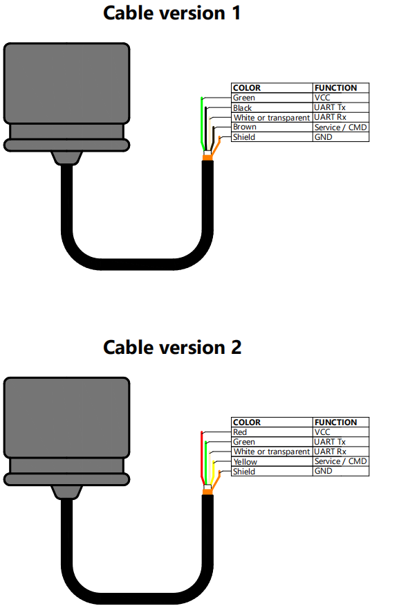
For the integrated version, use a USB-UART converter according to the pinout:
CAUTION! The voltage of the responder-beacon data lines is 0 .. 3.3 V! Use only converters with suitable levels to connect beacons to a PC.
 |
|---|
| Cable wire assignment of the Zima-R and Zima2-R responder-beacons |
After connecting the responder-beacon to the PC, launch the AzimuthSuite application and establish a connection by pressing the 🔌 LINK button (or the Ctrl + L key combination).
The application will search for the port; the progress and result of the search are displayed in the status line.
Once the connection has been successfully established, the 🛠 UTILS ⯈ 🤖 DEVICE ⯈ Responder settings… menu item becomes available.
In the address setup dialog box that opens, the following functions are available:
- determining the current beacon address (the 📤 QUERY button)
- setting the specified beacon address (the 📥 APPLY button)
Writing the new settings to the non-volatile memory of the responder-beacon takes from 1.5 to 3 seconds.