docs.unavlab.com
Main ❯ Other equipment ❯ F4105: User’s manual
 |
|
|---|---|
| www.unavlab.com support@unavlab.com |
F4105 Acoustic release User’s manual |
F4105
Acoustic release
User’s manual
Contents
- 1. F4105 system description
- 2. Working with the system
- 3. Storage and maintenance
- 4. Obligations and disclaimer
- Appendices
1. F4105 system description
1.1. Purpose
The system is an easy-to-use and functional solution for raising the line of bottom equipment deployed for a long period (up to 2 months). Uncoupling from the anchor is performed by a reliable screw mechanism, initiated by an addressed command transmitted over the underwater acoustic channel from the water surface (by means of a lowered transducer). After uncoupling, the lifting line unwinds from the float-reel, while the lower end of the line remains connected to the anchor (and the bottom equipment). This makes it possible to raise the bottom equipment by the upper end of the line.
1.2. System composition
The current version of the system consists of three devices:
- setting device: a standalone surface module designed to issue ascent commands and to set the address;
- control device: the acoustic wake-up unit, responsible for receiving the addressed signal and issuing the command to the actuator;
- actuating device: the actuator, containing a screw mechanism for uncoupling from the anchor and a power source, which also powers the control device
1.2.1. F4105-SU programming and control unit
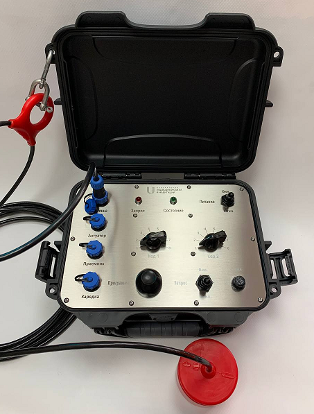
The programming and control unit is the setting device, designed for setting (programming) the addresses of acoustic wake-up units and issuing addressed commands to acoustic wake-up units. It is made in the form of an impact-resistant plastic case with a stainless steel front panel on which the controls are located. The appearance of the device is shown below:
 |
|---|
| Figure 1 - Programming and control unit for releases F4105-SU with a transducer on a cable |
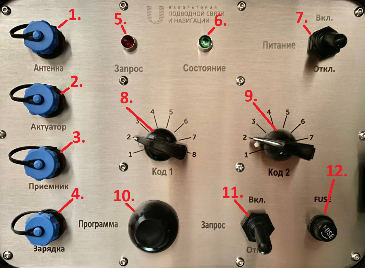
The figure below shows the front panel of the device with the controls:
 |
|---|
| Figure 2 - Controls of the F4105-SU unit |
| 1 - Transducer connector, 2 - Actuator test connector, 3 - Acoustic wake-up unit connector, 4 - Charger connector, 5 - Request indicator, 6 - Status indicator, 7 - Device power toggle switch, 8 - Code 1 switch, 9 - Code 2 switch, 10 - Button for writing the address into the acoustic wake-up unit, 11 - Request mode switch, 12 - Fuse holder |
1.2.2. F4105-AU acoustic wake-up unit
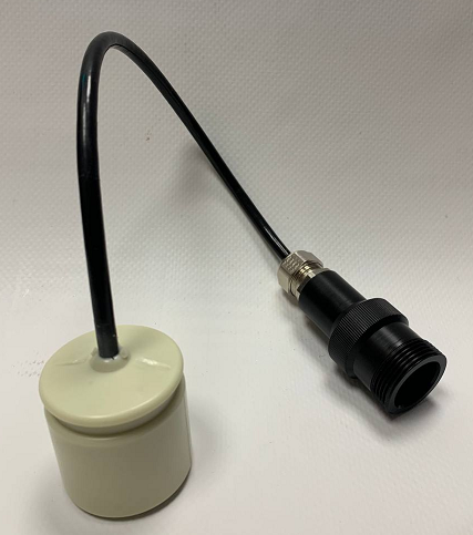
The acoustic wake-up unit is the control device that supplies a signal which switches on the actuating device (actuator) upon receiving an addressed request over the underwater acoustic channel. The acoustic wake-up unit is equipped with a cable and a connector for interfacing with the setting device for address programming and for interfacing with the actuating device. The appearance of the wake-up unit is shown in the figure below:
 |
|---|
| Figure 3 - Acoustic wake-up unit F4105-AU |
1.2.3. F4105-BU release unit
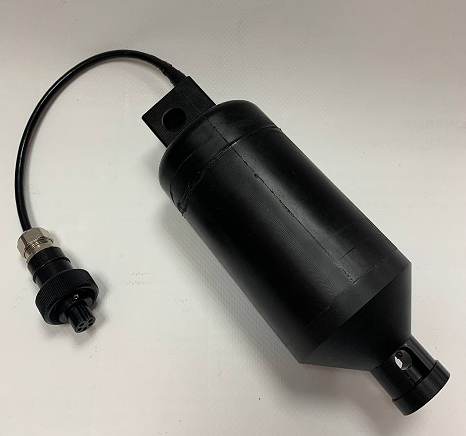
The release unit is both the actuating device and the power source. It is designed for uncoupling the device from the anchor by means of a screw mechanism. Upon receiving a signal from the control device, a geared motor is activated in the actuator, which unscrews the lock nut connected to the anchor and thereby allows the actuator with the float to rise under the action of the buoyant force.
The appearance of the release unit is shown in the figure below:
 |
|---|
| Figure 4 - Release unit F4105-BU |
The actuator has a connector on a cable for:
- connecting the control device (acoustic wake-up unit)
- connecting the charger
- connecting to the setting device for testing
1.4. Delivery set
The standard delivery set includes:
| Programming and control unit F4105-SU | 1 pc. |
|---|---|
| Underwater acoustic transducer type RT-1.524525-1 with a load-bearing eye | 1 pc. |
| Carabiner | 1 pc. |
| Rigging shackle | 1 pc. |
| Mains charger for the programming and control unit | 1 pc. |
| Adapter for connecting the acoustic wake-up unit | 1 pc. |
| Adapter for connecting the release unit | 1 pc. |
| Jumper with clamps | 1 pc. |
| Spare fuse | 1 pc. |
| Release unit F4105-BU with a lock nut | 1 pc. |
| Mains charger for the release unit | 1 pc. |
| Spare sealing ring (O-ring) for the lock nut | 1 pc. |
| Reel | 1 pc. |
| Reel cover | 1 pc. |
| Line 4 mm | 50 m |
| Lock nut pin | 1 pc. |
| Acoustic wake-up unit F4105-AU | 1 pc. |
| Stabilizer float | 1 pc. |
2. Working with the system
The typical operating sequence consists of the following stages:
- programming the address of the wake-up unit
- preparing the actuator with the wake-up unit for deployment together with the bottom equipment
- deploying the bottom equipment at the required point
- going to the required point and transmitting the ascent command
- hauling in the bottom equipment by the end of the line that has surfaced
2.1. Programming the address of the wake-up unit
Minimum set of equipment for programming the wake-up unit:
- F4105-SU programming and control unit, charged and in working order
- Adapter for connecting the wake-up unit
- F4105-AU wake-up unit to be programmed (to set the ascent code)
Procedure for programming the wake-up unit:
- Place the programming unit on a flat surface and open the lid by unlatching the catches on the sides of the case
- Make sure that the unit is switched off: toggle switch (7) Power is in the Off position
- Make sure that toggle switch (11) Request is in the Off position
- Connect the wake-up unit via the adapter to connector (3) Receiver
- Switch on the programming unit by setting toggle switch (7) Power to the On position
- Make sure that the unit has entered programming mode, namely, that indicator (6) Status blinks frequently
- If the unit has not entered programming mode (indicator (6) Status is not blinking), the acoustic wake-up unit cannot be programmed. Try repeating the steps. If the situation repeats, contact support
- Keep in mind that the unit automatically exits programming mode 2 minutes after being switched on. If the wake-up unit has not been programmed within this time, switch off the unit by setting toggle switch (7) Power to the Off position and repeat the steps starting from step 2.
- Use switches Code 1 (8) and Code 2 (9) to set the new wake-up code that will be programmed into the wake-up unit
- Press button (10) Program
- If the wake-up unit has been programmed successfully, indicator (6) Status stops blinking and stays lit continuously for two seconds, after which it starts blinking again, signaling readiness for programming
- If an error occurred during programming, indicator (5) Request will light up for two seconds. In this case, try repeating all the steps from the beginning. If the error repeats, contact support
- Switch off the programming unit by setting toggle switch (7) Power to the Off position
- Disconnect the wake-up unit from connector (3) Receiver
- To program another wake-up unit, repeat the steps starting from step 2.
⚠ CAUTION! It is strongly recommended to keep a list that matches the factory number of the wake-up unit, the code programmed into it, and the place and date of deployment. This will help avoid a situation in which the bottom equipment cannot be recovered because the ascent code has been lost. Given the total number of possible addresses, in this situation the equipment can be raised only directly (for example, by divers) or by trying the possible codes. A sample form for keeping such a list is given in the Appendices.
2.2. Checking the wake-up unit and the actuator
This procedure checks:
- The correctness of the programmed code (or the code is determined)
- The operability of the underwater acoustic transmitter of the programming and control unit
- The operability of the acoustic wake-up unit
- The operability of the release unit
Minimum set of equipment for checking the wake-up unit and the actuator:
- F4105-SU programming and control unit, charged and in working order
- Adapter for connecting the wake-up unit
- F4105-AU wake-up unit
- Adapter for connecting the actuator
- F4105-BU release unit, charged and in working order
- Jumper with clamps
Before performing the checks, the equipment must be inspected for:
- damage and/or wear of any rubber seals
- foreign objects and/or contamination on the elements of the threaded connection of the actuator and the lock nut, as well as on the connectors
- damage to the cable insulation
- damage to connector parts
- extensive traces of corrosion on the connector elements
⚠ CAUTION! If at least one item from the list above is found, further checking of the equipment must be canceled, the equipment must be recognized as defective, and its further use until the fault is eliminated is completely prohibited!
Procedure for checking the wake-up unit and the actuator:
- Place the programming unit on a flat surface and open the lid by unlatching the catches on the sides of the case
- Make sure that the unit is switched off: toggle switch (7) Power is in the Off position
- Make sure that toggle switch (11) Request is in the Off position
- Connect the wake-up unit via the adapter to connector (3) Receiver
- Connect the release unit via the adapter to connector (2) Actuator; the lock nut of the actuator must be screwed in
- With the wake-up unit and actuator connected, use the jumper with clamps to connect the metal parts of their connectors to each other
- Connect the transducer to the programming and control unit via connector (1) Antenna
- Place the transducer and the body of the wake-up unit no more than 4 cm from each other, for example on the surface of a table
- Switch on the programming and control unit by setting toggle switch (7) Power to the On position
- Make sure that the unit has entered programming mode, namely, that indicator (6) Status blinks frequently
- If the unit has not entered programming mode (indicator (6) Status is not blinking), switch off the unit by setting toggle switch (7) Power to the Off position and repeat the steps starting from step 2. If the situation repeats, contact support.
- Wait for approximately 2 minutes for the unit to exit programming mode, which will be indicated by indicator (6) Status ceasing to blink and staying lit continuously
- If the unit does not exit programming mode after approximately two minutes, switch off the unit by setting toggle switch (7) Power to the Off position and repeat the steps starting from step 2. If the situation repeats, contact support.
- Use switches Code 1 (8) and Code 2 (9) to set the code corresponding to this wake-up unit
- Note the position of the lock nut of the actuator and indicator (5) Request
- Set toggle switch (11) Request to the On position
- Indicator (5) Request is lit while the underwater acoustic initiating signal is being emitted
- When the correct code is received, the actuator motor will be switched on for approximately 2 seconds.
- If the actuator motor switches on, the system is considered serviceable and operational.
- If the motor does not switch on, check that the code set with switches (8) and (9) is correct.
- Set toggle switch (11) to the Off position
- Switch off the unit by setting toggle switch (7) Power to the Off position
- Disconnect the wake-up unit and the actuator from the unit
- To check another set of equipment, repeat the steps starting from step 2.
The actuator with the wake-up unit can also be checked without connecting them to the programming and control unit, but in this case the motor will be switched on for 90 seconds. To perform such a check, which in effect fully simulates the operation of the system in air, perform the following sequence of actions:
- Place the programming unit on a flat surface and open the lid by unlatching the catches on the sides of the case
- Make sure that the unit is switched off: toggle switch (7) Power is in the Off position
- Make sure that toggle switch (11) Request is in the Off position
- Connect the transducer to the programming and control unit via connector (1) Antenna
- Connect the acoustic wake-up unit to the actuator using the connector and make sure that the lock nut of the actuator is screwed in
- Connect the metal parts of the connectors of the wake-up unit and the actuator using the jumper with clamps (the connector may be immersed in a container of water so that the metal parts of both halves of the connector are completely submerged throughout the check)
- Place the transducer and the body of the wake-up unit no more than 4 cm from each other, for example on the surface of a table
- Use switches Code 1 (8) and Code 2 (9) to set the code corresponding to this wake-up unit
- Switch on the programming and control unit by setting toggle switch (7) Power to the On position
- Set toggle switch (11) Request to the On position
- Indicator (5) Request is lit while the underwater acoustic initiating signal is being emitted
- When the correct code is received, the actuator motor will be switched on for approximately 90 seconds
- If the actuator motor switches on, the system is considered serviceable and operational
- If the motor does not switch on, check that the code set with switches (8) and (9) is correct
- Set toggle switch (11) to the Off position
- Switch off the unit by setting toggle switch (7) Power to the Off position
- Disconnect the wake-up unit and the actuator from the unit
- To check another set of equipment, repeat the steps starting from step 2.
2.3. Preparing the release for deployment
At this stage, it is assumed that:
- the actuator is fully charged;
- the required address has been programmed into the wake-up unit;
- all the required checks described in the sections above have been performed;
Preparation for deployment consists of the following steps:
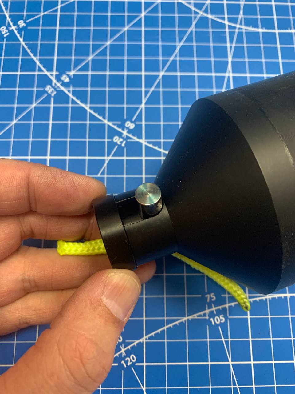
- Step 1. Make sure that the lock nut is screwed into the actuator as far as it will go and that its hole is aligned with the groove in the actuator housing (the lock pin enters the hole freely)
 |
|---|
| Figure 5 - The lock nut is screwed onto the actuator shaft |
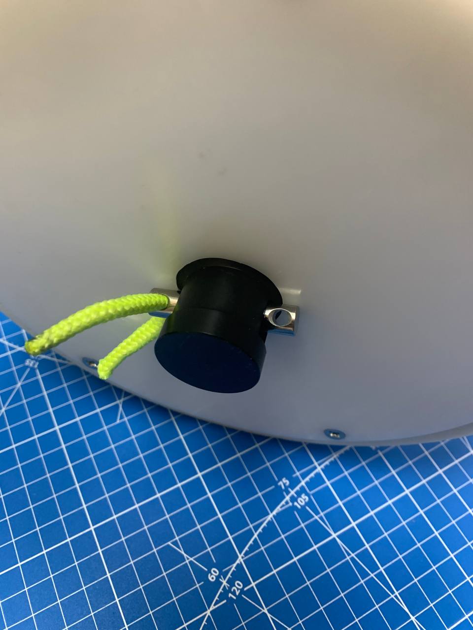
- Step 2. Insert the actuator into the reel with the lock nut facing the round hole (toward the bottom of the reel) and temporarily secure it with the lock pin
 |
|---|
| Figure 6 - The actuator is inserted into the reel |
- Step 3. Prepare the cord (rope) for laying and make sure that:
- the cord is completely dry
- it has no damage or knots
- the end of the cord is finished (for example, by melting)
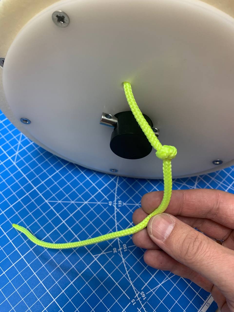
- Step 4. Pass the end of the cord through the special hole in the bottom of the reel
- Step 5. Let out approximately 50 centimeters of cord and tie a stopper knot
 |
|---|
| Figure 7 - The cord is passed through the hole in the bottom of the reel |
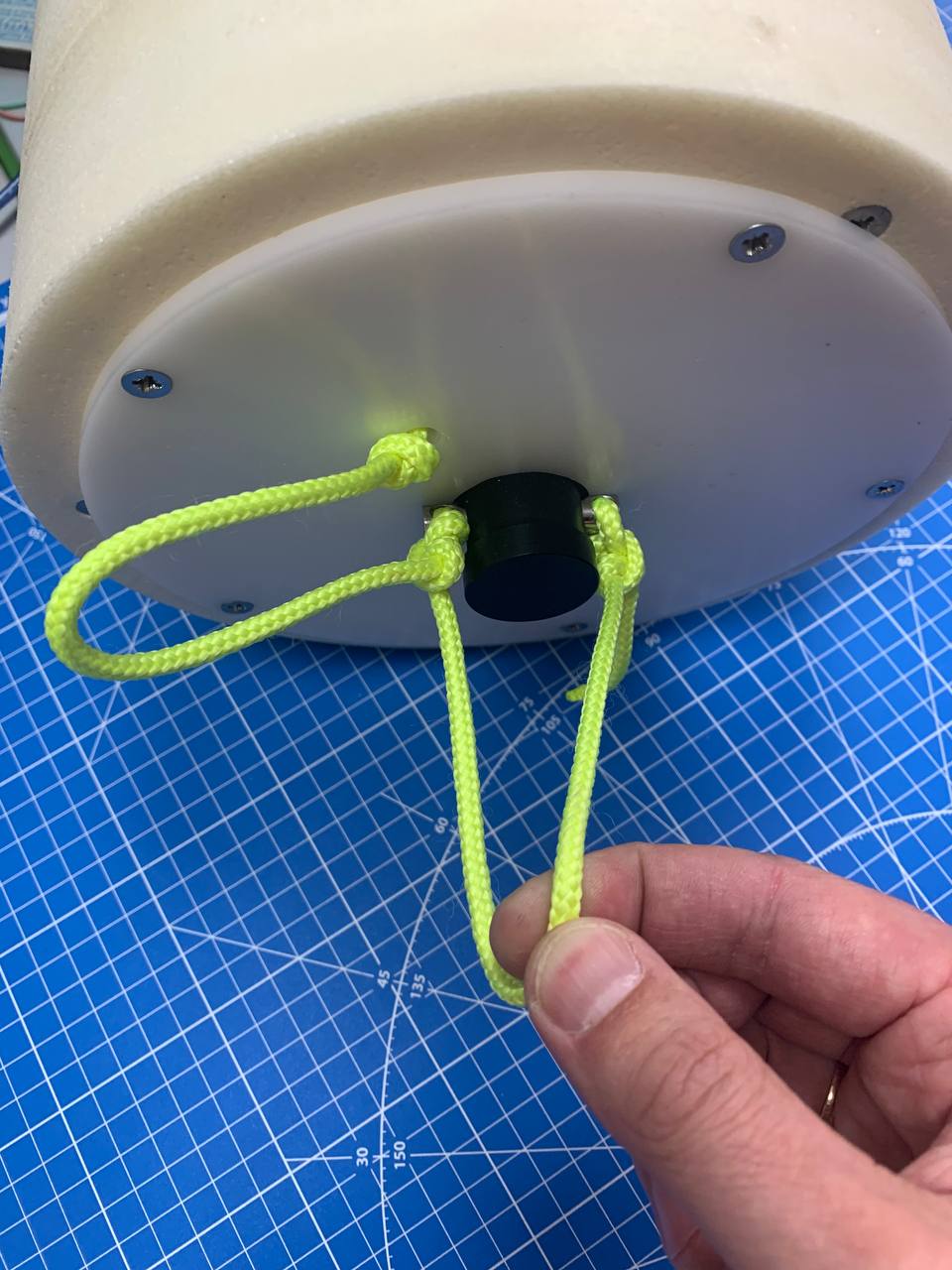
- Step 6. Secure the end of the cord that extends from the reel to the lock pin, forming a loop for attaching the anchor, as shown in the figure
 |
|---|
| Figure 8 - The cord is secured to the lock pin, the anchor loop is formed |
- Step 7. Place the reel upright for laying the cord
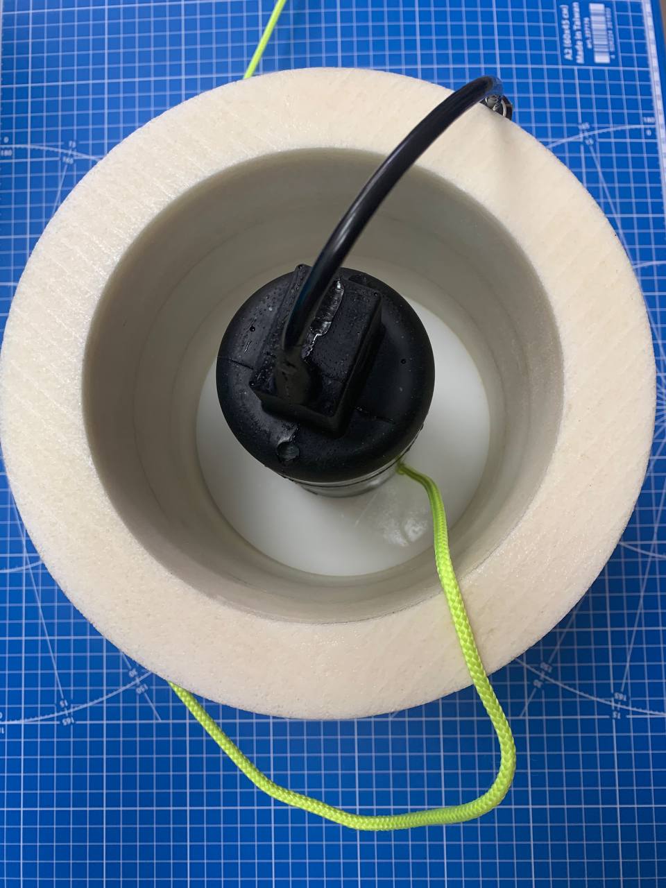 |
|---|
| Figure 9 - Start of laying the cord into the reel |
- Step 8. Lay the cord loosely, as shown in the figure, preventing it from tangling and from winding around the actuator
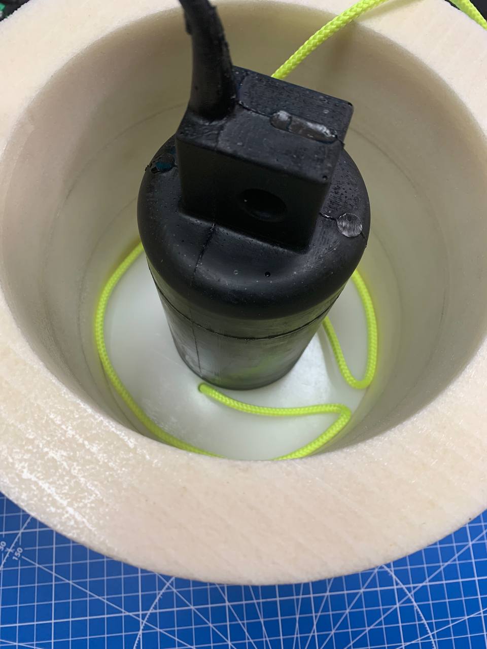 |
|---|
| Figure 10 - Laying the cord into the reel |
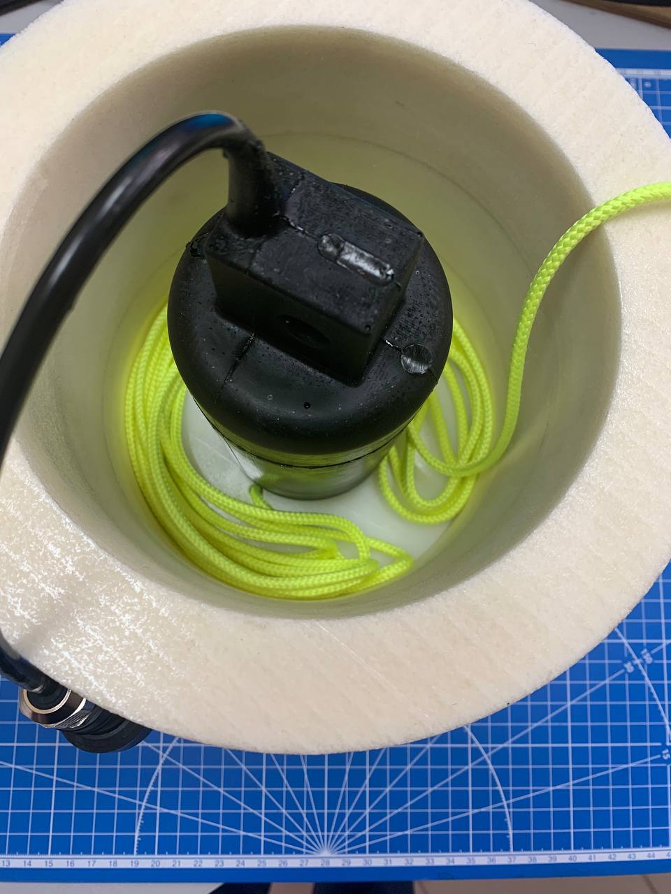 |
|---|
| Figure 11 - Laying the cord into the reel |
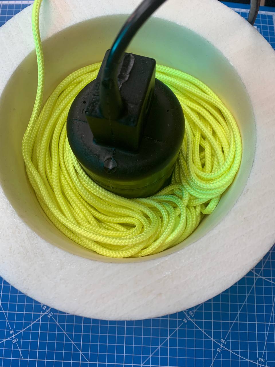 |
|---|
| Figure 12 - Laying the cord into the reel |
- Step 9. When the cord has been laid, leave 50–100 centimeters at the end of the cord and tie a stopper knot
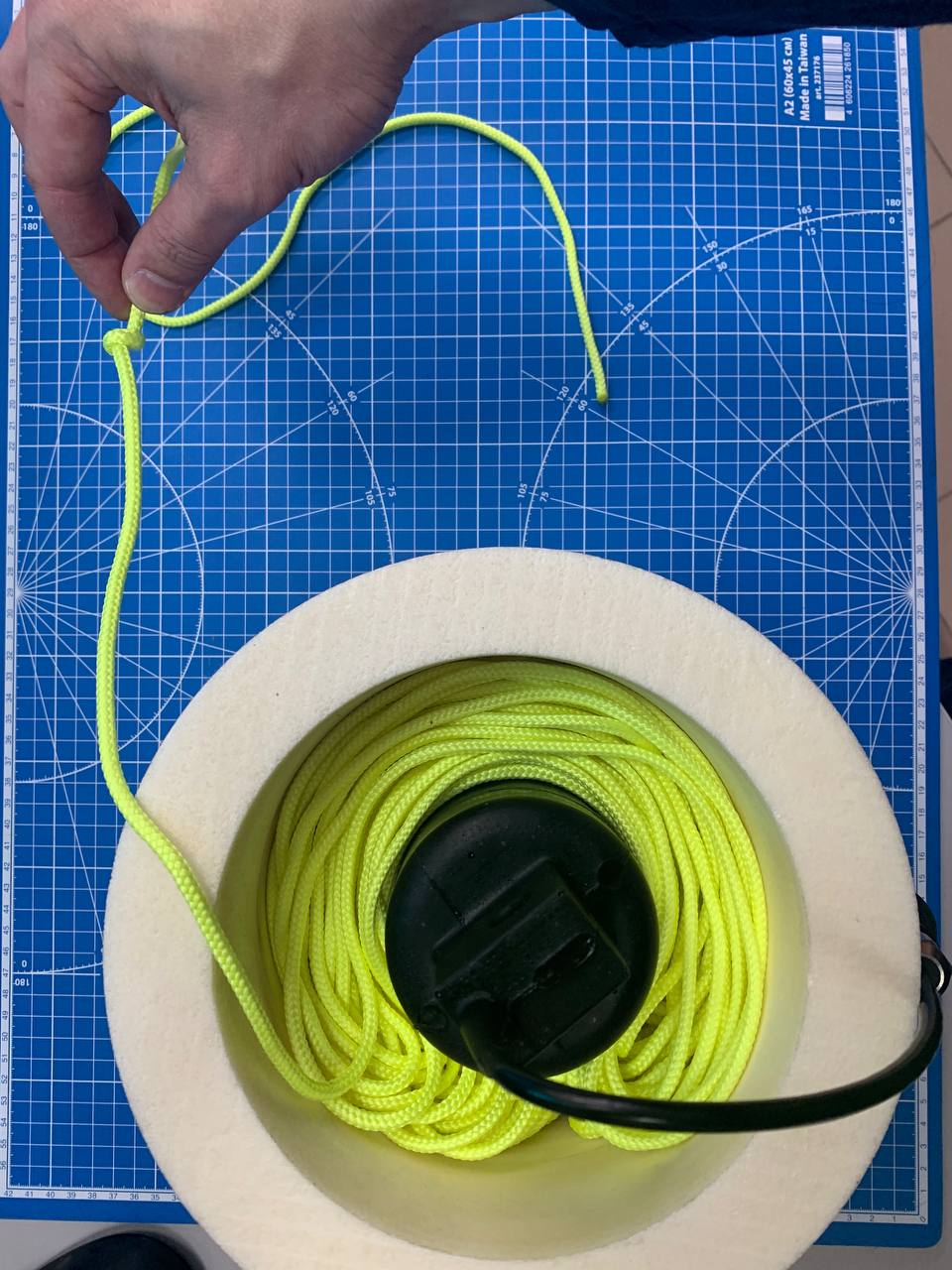 |
|---|
| Figure 13 - Free (upper) end of the cord |
- Step 10. Pass the end of the cord through the reel lid
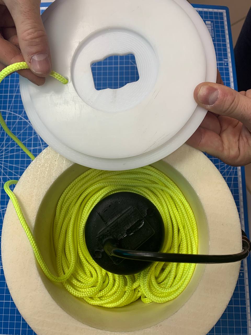 |
|---|
| Figure 14 - Putting on the reel lid |
- Step 11. Pass the actuator connector through the lid and connect the wake-up unit
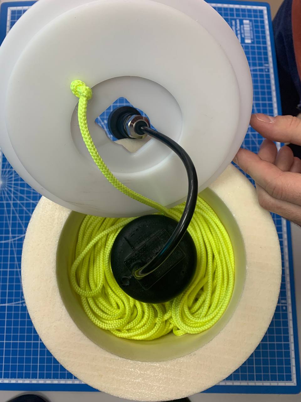 |
|---|
| Figure 15 - Stopper knot |
- Step 12. Close the lid and secure it with the free end of the cord, forming a loop for attaching the float
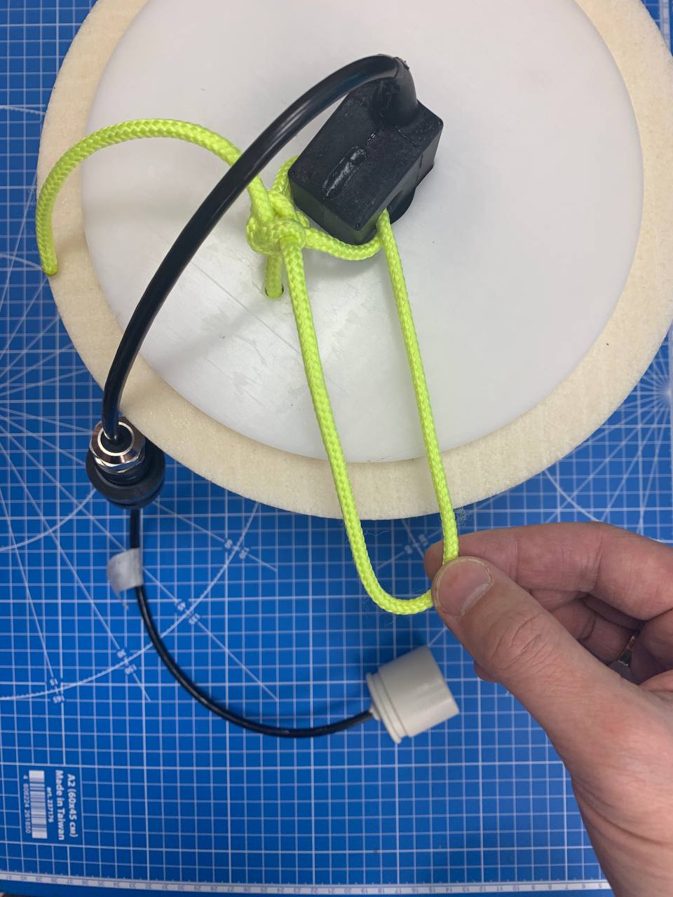 |
|---|
| Figure 16 - Securing the reel lid with the cord and forming the upper loop |
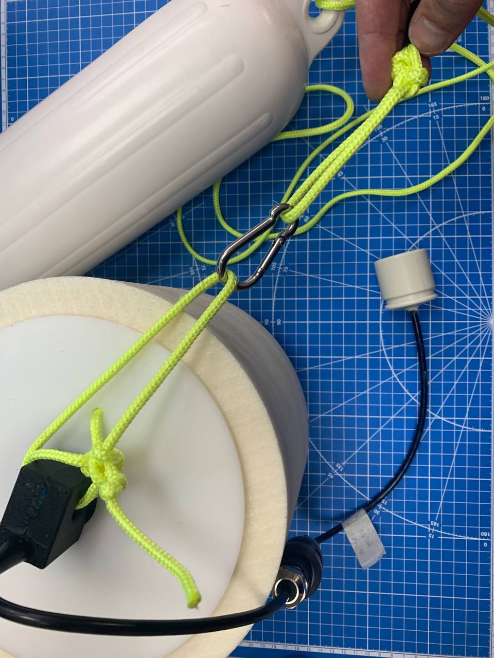
- Step 13. Attach the float to the loop using the carabiner. The length of the float cord must be greater than the length of the cable of the acoustic wake-up unit so that the wake-up unit is not covered by the float
 |
|---|
| Figure 17 - Attaching the float |
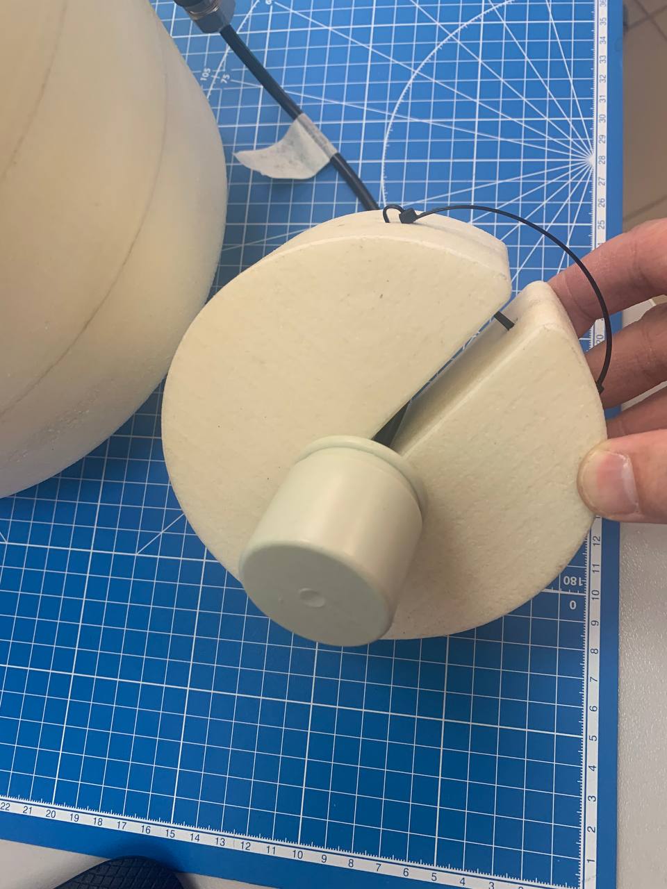
- Step 14. Put the small float onto the cable of the wake-up unit and secure it with a cable tie. The small float is needed to keep the wake-up unit vertical when submerged
 |
|---|
| Figure 18 - Attaching the small float (stabilizer float) |
- Step 15. Attach the bottom equipment to the loop on the lock nut
- Step 16. The release is ready for deployment. During deployment, it is recommended to keep the reel upright
Deploy the equipment gradually, making sure that the cables and cords do not become tangled. The anchor must be lowered first (if there is one and if the bottom equipment is not heavy enough).
2.4. Transmitting the ascent command
Ascent commands are transmitted after reaching the area of the body of water where the bottom equipment fitted with F4105 releases is located. For commands to be transmitted successfully and received by the acoustic wake-up unit, there must be no more than 200 meters in a straight line between the transducer of the programming and control unit and the housing of the acoustic wake-up unit, with a direct line of sight (through the water column): there must be no natural or artificial obstacles between the transmitter and the receiver, such as vessels with a low draft, underwater and port infrastructure objects, bridge piers, elements of the bottom landscape and vegetation.
After reaching the area where the release to be raised is installed, follow the instructions below:
- Install the programming and control unit, securing it firmly on the vessel so that it cannot tip overboard
- Open the lid of the unit by unlatching the catches on the sides of the case
- Make sure that the unit is switched off: toggle switch (7) Power is in the Off position
- Make sure that toggle switch (11) Request is in the Off position
- Keep the vessel stationary (slight drift is permitted) to prevent the transducer of the programming and control unit from floating up
- Connect the transducer to connector (1) Antenna of the unit and secure it by its load-bearing eye to the case lid, or in another way that prevents it from sinking
- Lower the transducer overboard to a depth of at least one meter and no higher than one meter from the lowest point of the vessel
- Set toggle switch (7) Power to the On position
- Use switches Code 1 (8) and Code 2 (9) to set the code corresponding to this wake-up unit
- Set toggle switch (11) Request to the On position
- Indicator (5) Request is lit while the underwater acoustic initiating signal is being emitted
- Observe the surroundings, waiting for the buoy with the release (actuator, wake-up unit) to surface.
- When the surfacing of the buoy is observed, set toggle switch (11) Request to the Off position unless work with other releases is planned
- If the ascent of the release cannot be initiated within half an hour, make sure that the vessel is within the 200-meter zone around the release (the vessel may have been carried out of the zone by drift, etc.)
⚠ CAUTION! When removing the equipment from the water, it is prohibited to pull the wake-up unit or to apply any force to the cable!
⚠ CAUTION! If the programming and control unit is switched on while toggle switch (11) Request is in the On position (which is not recommended), a pause of approximately 30 seconds will be observed immediately before the device enters the Request mode, during which indicator (5) Request will blink.
2.5. Recommended procedures immediately after the release is recovered
After the equipment has been raised, it is necessary to:
- desalinate and rinse the equipment in fresh water to remove contamination and biofouling, especially if the equipment has been in seawater
- thoroughly rinse and dry the threaded connection of the lock nut and the nut itself; after drying, the nut and the hole in the actuator must be lubricated with thick silicone grease, and the nut must be screwed in to prevent dust and moisture from getting into the threaded connection and onto the seals
- it is prohibited to store actuators and wake-up units together with the float-reel and the line
3. Storage and maintenance
3.1. Storage and maintenance conditions
- All equipment must be stored switched off and completely dried
- Underwater and submersible parts must be desalinated and rinsed before being put into storage and/or transported; all contamination must be removed with warm fresh water
- The use of organic solvents and aggressive detergents is prohibited
- The actuator is stored with the lock nut screwed in and the seals lubricated with thick silicone grease
- The actuator and the wake-up unit are stored disconnected; it is recommended to put a plastic bag on the connector parts to prevent the grease on the seals from drying out and to keep out dust, moisture and contamination
- Bending the cables of the devices to a radius of less than 5 cm is prohibited.
3.2. Charging the built-in power supplies
The built-in power supplies are charged with the supplied chargers. Chargers from different equipment sets are compatible with each other for devices of the same type.
The chargers are designed for connection to the AC mains and indicate two states:
- Charging
- Not charging
The specific indication method may vary depending on the specific model and manufacturer of the mains charger. Therefore, to determine it, read the information on the housing of the device or, if none is provided, perform a simple check:
- Connect the charger to the mains without a load (without the device to be charged)
- The indication while the charger is operating without a load signals the “not charging” state
- Disconnect the charger from the mains
- Connect a load (the device to be charged) to the charger
- Connect the charger to the mains
- The indication while the charger is operating under load signals the “charging” state
Charge the devices until the charger signals that charging is complete.
During long-term storage, the built-in power supplies must be charged with the supplied chargers at least 1 time every 6 months. Before being put into storage, all devices with built-in power supplies must be fully charged.
4. Obligations and disclaimer
4.1. Terms of replacement and free warranty service
The manufacturer’s warranty covers only factory defects that become apparent during operation of the device in accordance with this manual during the warranty period (2 years from the date of purchase).
The manufacturer guarantees free repair or replacement of faulty equipment from the delivery set specified in section 1.4. that has failed due to a factory defect.
Grounds for refusing free warranty service, free repair and replacement include:
- any mechanical damage to the equipment from the delivery set specified in section 1.4., including damage to the insulation of wires and cables;
- any damage caused by exposure to moisture and contamination due to improper operation of the equipment from the delivery set specified in section 1.4.;
- any electrical damage caused by the use of accessories not included in the delivery set (charger), or by the use of poor-quality and/or failed batteries; accessories supplied by the manufacturer or its representative to replace faulty or lost ones are not considered to be outside the delivery set;
- any signs of unauthorized repair and/or opening of the equipment from the delivery set specified in section 1.4..
4.2. Limitation of the manufacturer’s liability
ANY OF THE PARTS OF THE DELIVERY SET ACCORDING TO section 1.4., INDIVIDUALLY AND AS PART OF THE SYSTEM, HEREINAFTER REFERRED TO AS THE “SUPPLIED EQUIPMENT”:
- WAS NOT DESIGNED AS RESCUE EQUIPMENT
- WAS NOT TESTED AS RESCUE EQUIPMENT
- IS NOT RESCUE EQUIPMENT
- THE MANUFACTURER DECLARES THAT THE SUPPLIED EQUIPMENT IS SAFE WHEN OPERATED IN ACCORDANCE WITH THESE INSTRUCTIONS, AND THE MANUFACTURER IS NOT RESPONSIBLE FOR ANY CONSEQUENCES OF THE USE OF THE SUPPLIED EQUIPMENT
Appendices
Bottom equipment installation form No.
| Device | Factory number | Note |
|---|---|---|
| F4105-AU wake-up unit | ||
| F4105-BU actuator |
| No. | Latitude of installation site | Longitude of installation site | Installation date | Code | Removal date | Note |
|---|---|---|---|---|---|---|
| 1 | ||||||
| 2 | ||||||
| 3 | ||||||
| 4 | ||||||
| 5 | ||||||
| 6 | ||||||
| 7 | ||||||
| 8 | ||||||
| 9 | ||||||
| 10 | ||||||
| 11 | ||||||
| 12 | ||||||
| 13 | ||||||
| 14 | ||||||
| 15 | ||||||
| 16 | ||||||
| 17 | ||||||
| 18 | ||||||
| 19 | ||||||
| 20 |