docs.unavlab.com
 |
|
|---|---|
| www.unavlab.com support@unavlab.com |
RedPhone-D Underwater telephone. Diver’s unit User’s manual |
RedPhone-D
Underwater telephone. Diver’s unit
User’s manual
Contents
- 1. RedPhone-D: Device description
- 2. Using the device
- 3. Storage and maintenance
- 4. Liability and disclaimer
1. RedPhone-D: Device description
1.1. Purpose
Diver’s wireless voice communication unit RedPhone (hereinafter - the station) is intended for the wireless exchange of voice messages between divers, as well as divers and a surface control station, equipped with diving communication devices that maintain signal parameters common with the station.
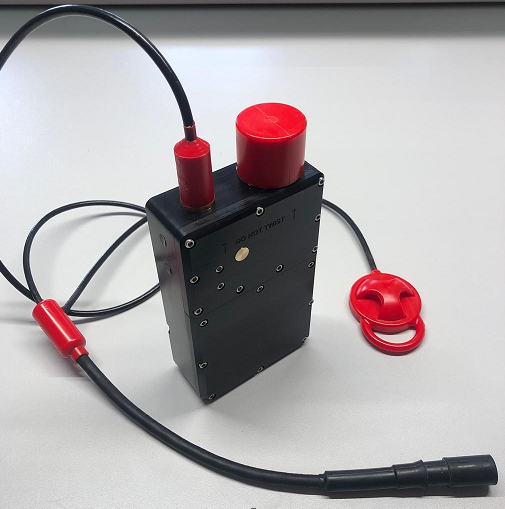
The general view of the station RedPhone is shown in Figure 1.
|
|---|
| Figure 1 - RedPhone general view |
The device is made in a plastic case with a serviceable battery compartment, where rechargeable batteries of 18650 type are located. On the upper part of the device, there is a hydroacoustic transceiver antenna and a cable entry with a cable and a connector for a telephone headset with a push-to-talk (PTT) button. Versions are possible both for headsets with built-in push-to-talk button, and without it, in this case, the device can be equipped with its own push-to-talk button.
1.2. Controls and Connectors
The device does not contain external controls and turns on automatically when it submerged into the water. Charging is performed with a complete cradle (chassis) with a charger. Switching channels and switching on the compatibility mode with the navigation tracking system RWLT is carried out using a DIP-switch located in the battery compartment.
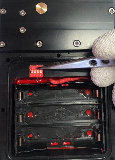
Figure 2 shows the location of the channel selector and the compatibility mode with the RWLT navigation system.
 |
|---|
| Figure 2 - The location of the channel selector in battery compartment |
Table 1 describes the functions of the switch sections.
Table 1 - Switch Section Functions
| Section number | Function |
|---|---|
| 1 | RWLT navigation system compatibility mode |
| 2 | Channel selector - bit 2 |
| 3 | Channel selector - bit 1 |
| 4 | Channel selector - bit 0 |
1.3. Technical specifications
The station uses single sideband amplitude modulation (engl. SSB, Single side band) and supports the bands most commonly used in such systems, which ensures compatibility with almost all analogs. Table 2 shows the correspondence of station channel numbers and frequency bands.
Table 2 - Correspondence of channel number, position of switch sections and signal parameters
| Channel number | Bit 2 | Bit 1 | Bit 0 | Carrier, Hz | Side band | Bandwidth, Hz |
|---|---|---|---|---|---|---|
| 1 | 0 | 0 | 0 | 32768 | Lower | 28468 .. 32468 |
| 2 | 0 | 0 | 1 | 32768 | Upper | 33068 .. 37068 |
| 3 | 0 | 1 | 0 | 31250 | Lower | 26950 .. 30950 |
| 4 | 0 | 1 | 1 | 31250 | Upper | 31550 .. 35550 |
| 5 | 1 | 0 | 0 | 28500 | Lower | 24200 .. 28200 |
| 6 | 1 | 0 | 1 | 28500 | Upper | 28800 .. 32800 |
| 7 | 1 | 1 | 0 | 25000 | Lower | 20700 .. 24700 |
| 8 | 1 | 1 | 1 | 25000 | Upper | 25300 .. 29300 |
General technical specifications of the device are shown in table 3:
Table 3 - Technical specifications
| PARAMETER | VALUE |
|---|---|
| DIMENSIONS1 | 203 x 105 x 45 mm |
| WEIGHT2 (dry) | 1.55 kg |
| MAX. DEPTH | 70 m |
| MAX. OPERATING RANGE3 | 1000 m |
| ACOUSTIC SOURCE LEVEL | 150 dB re 1 uPa @ 1 m |
| VOICE BANDWIDTH4 | 300 .. 4300 Hz |
| NUMBER OF SUPPORTED CHANNELS | 8 |
| BATTERY LIFE (RX MODE)5 | up to 80 hours |
| BATTERY LIFE (MIXED MODE)5, 6 | up to 2 hours |
| BATTERY LIFE (MIXED MODE)5, 7 | up to 2.5 hours |
| WORKING TEMPERATURE RANGE | 0 .. 50° С |
| BATTERIES | 3 x 18650 Li-Ion |
| CHANNEL SWITCHING | DIP-switch in the battery compartment |
| BODY MATERIAL | Delrin |
| CABLES INSULATION MATERIAL | Polyurethane |
| NAVIGATION SIGNAL CARRIER8 | 20050 Hz |
| NAVIGATION SIGNAL MODULATION TYPE | BPSK |
| NAVIGATION SIGNAL DURATION | 200 msec |
1 Including transducer.
2 With a battery, a PTT and a mask connector, deepending on the specific connector, the value may differ by the weight of the connector.
3 A parameter that determines the maximum range at which a signal can be received based on the electro-acoustic parameters of the transmitter and receiver, spatial decrease in the intensity of sound energy, attenuation in the medium and level of acoustic noise.
4 The actual audible frequency range depends on the headset used.
5 With new, fully charged batteries with a capacity of 3000 mA*h or more, at an ambient temperature of 20 °C.
6 While transmitting 2 minutes per 10 minutes.
7 While transmitting 5 minutes per 10 minutes.
8 The function is provided by buoys of the RWLT navigation system.
1.4. Equipment set
Table 4 - equipment set
| № | Item | Quantity | Description |
|---|---|---|---|
| 1 | RedPhone-D with belt clip and headset connector | 1 pcs. | |
| 2 | Charger with cradle | 1 pcs. | |
| 3 | SPTA kit (bit for a hex nut, a set of bolts and nuts, spare o-ring seal) | 1 pcs. |
2. Using the device
2.1 Preliminary checks
Before immersing the appliance in water, it is the user’s responsibility to ensure that:
- the battery compartment of the device is tightly screwed;
- a headset is connected to the connector (connector is connected);
- the device is securely fastened with a strap to the tank (recommended attachment point) or to the diver’s belt.
Before starting work, the user must:
- check the correctness of the selected communication channels on all devices participating in the work in the immediate vicinity according to paragraphs 2.2.2. и 2.2.3..
2.2. Working mode
Before work, all preparations and checks must be accomplished provided in 2.1..
Diver’s wireless voice communication works on a half-duplex scheme: transmission and reception alternate, if the device is in transmission mode, it cannot receive incoming messages.
2.2.1. Sound alerts
Possible sound alerts are summarized in Table 5.
Table 5 - Sound alerts
| Alert | Meaning |
|---|---|
| Short rising and then falling tone | On power on |
| Short rising tone | Switching to the receive mode |
| Short falling tone (~ every 30 seconds) | Internal power supply low |
2.2.2. Receiving voice messages
To receive voice messages from divers, the PTT button on the headset must be released. In this case, incoming messages will be played by the headset.
The volume of the reproduced incoming voice messages depends on the distance between the acoustic antennas, on hydrological conditions. It may decrease when the diver enters the acoustic shadow zone (when elements of the underwater landscape, parts of structures, ships, algae, etc. are on the signal path).
2.2.3. Transmitting voice messages
To transmit voice messages, the following sequence of actions is performed:
- Press the PTT on the headset;
- Wait for a short pause (~0.5 seconds) for the station to switch to transmission mode;
- Pronounce voice messages with good articulation; It is recommended to end the voice message with “Roger” or “Copy” etc., signalling the addressee that the message is over;
- Take a short pause (~0.5 seconds);
- Release the PTT;
- The station emits a short beep indicating that the device has switched to the receiving mode if the compatibility mode with the navigation system RWLT is disabled or emits a navigation signal using the acoustic antenna if compatibility mode with the navigation system RWLT is enabled.
2.3. Finishing work
Upon completion of the work, the diving station does not require any additional manipulations and turns off automatically in the air. Before placing in the shipping container, it is necessary to rinse and/or desalinate in fresh water, followed by wiping with an absorbent cloth and air drying for at least 30 minutes.
3. Storage and maintenance
3.1. Storage and maintenance conditions
The station does not need special storage conditions, except for the following:
- Storage at temperatures from -20 ° to 60 °C;
- The headset connector must be disconnected;
- In case of long-term storage (more than a month), it is recommended to recharge the station’s built-in power supply;
- To remove impurities from the body of the device and after working in seawater, rinsing in freshwater is required. It is allowed to use a weak solution of household detergents with the battery compartment cover closed; When flushing, avoid getting moisture and / or detergents into the open connector of the headset;
- Bending of cables with a radius of less than 5 cm is not allowed;
- The application of torsion forces to the acoustic antenna or cable entry is not allowed;
- Before placing the device in the shipping container, moisture on the device must be completely removed.
PROHIBITED:
- OPENING EQUIPMENT FROM THE DELIVERY SET ACCORDING TO p. 1.4.
- ACCESS TO USE OF EQUIPMENT FROM THE DELIVERY SET ACCORDING TO p. 1.4. PERSONS WHO ARE NOT FAMILIAR WITH THESE INSTRUCTIONS
- ACCESS TO USE OF EQUIPMENT FROM THE DELIVERY SET ACCORDING TO p. 1.4. PERSONS UNDER THE ADVANCED
3.2. Charging the device
Charging of the built-in power supply of the station is allowed only with the charger from the equipment set when the headset connector is disconnected. Before using the charger, read the operating instructions for the charger. To charge the device, you must install it in the charging cradle and connect the complete charger in the household electrical network. The end of the charge is determined by the indicator of the charger from the equipment set.
3.3. Battery replacement
The device has a serviceable battery compartment, which houses 3 Li-Ion batteries of size 18650. Dismantling of the battery compartment cover should only be carried out by qualified persons and only to change channel settings and/or switch compatibility with the RWLT navigation system, and also for replacing batteries at the end of their service life. It is highly discouraged to frequently open and close the battery compartment in order to quickly replace discharged batteries with charged ones: the user must monitor the state of charge of the batteries and charge them in a timely manner, especially before use
To remove and install the cover of the battery compartment:
- place the device on the table, placing it on the narrow side, with the antenna away from you;
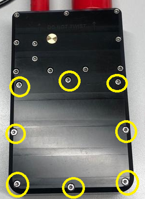
- using the supplied bit and a hex screwdriver h2.5 mm, loosen (by 3-4 turns) 8 cover screws one by one (see Figure 3);
- completely unscrew the cover screws;
- remove the bolts and nuts, remove the cover;
- place the device horizontally;
- if necessary, carefully remove the batteries, if necessary, prying them from behind with a flat non-conductive tool;
- if necessary, carefully install new batteries, observing the polarity of the installation;
- if necessary, configure the device using the switch;
- make sure that the sealing ring is intact and, if necessary, lubricate it with a thick silicone grease;
- make sure that there are no foreign objects (debris, hairs, etc.) on the O-ring and groove;
- install the cover of the battery compartment;
- insert the bolts;
- pressing the cover by hand, turn the device on its edge and tighten 4 nuts on the edges of the cover;
- slightly tighten the nuts to prevent slipping of the sealing ring;
- install the remaining nuts and tighten them completely so that there are no gaps between the cover and the body.
 |
|---|
| Figure 3 - Location of screws of the battery compartment cover |
WARNING !!!
It is strictly forbidden to unscrew any other screws and nuts on the device, except for those that secure the battery compartment cover! This may damage the device!
4. Liability and disclaimer
4.1 Terms of replacement and free warranty service
The manufacturer’s warranty applies only to factory defects that were discovered during the operation of the device in accordance with this manual during the warranty period (2 years from the date of purchase).
The manufacturer guarantees free repair or replacement of faulty equipment from the equipment set that has failed due to a factory defect.
The reasons for refusing free warranty service, free repair and replacement include:
- any mechanical damage of the equipment supplied according to p. 1.4., Including violation of insulation of wires and cables;
- any damage caused by exposure to moisture and pollution due to improper use of the equipment from the equipment set according to p. 1.4.;
- any electrical damage caused by use of not original accessories (charger, headset etc.);
- any signs of self-repair and/or opening of the equipment from the equipment set according to p. 1.4..
4.2 Disclaimer of the manufacturer
ANY OF THE PARTS OF THE EQUIPMENT SET ACCORDING TO par. 1.4. SEPARATELY AND IN THE COMPOSITION OF THE SYSTEM, NAME FURTHER “DELIVERED EQUIPMENT”:
- ARE NOT DESIGNED FOR WATER RESCUE USE
- NOT TESTED AS RESCUE EQUIPMENT
- NOT RESCUE EQUIPMENT
- THE MANUFACTURER DECLARES THAT THE DELIVERED EQUIPMENT IS SAFE WHEN OPERATING ACCORDING TO THESE INSTRUCTIONS AND IS NOT RESPONSIBLE FOR ANY CONSEQUENCES OF USE OF THE DELIVERED EQUIPMENT