docs.unavlab.com
| www.unavlab.com support@unavlab.com |
Zima USBL - underwater acoustic tracking system User’s manual |
THIS DOCUMENT IS UNDER CONSTRUCTION
Zima USBL
User’s manual
Contents
- 1. Introduction
- 2. Composition of the system
- 3. ZHost software
- 4. Effective use of the Zima USBL navigation system
- 5. Possible malfunctions, their diagnosis and elimination
- 6. Liability and disclaimer
1. Introduction
Underwater acoustic navigation and tracking system Zima is designed to determine in real-time the horizontal angle and distance to underwater objects equipped with responder-beacons Zima-R. Responder-beacons can be installed on remote-operated underwater vehicles (ROVs), inhabited underwater vehicles, autonomous unmanned underwater vehicles (AUVs) as well as for divers and technical divers (in case of using an autonomous version of the responder-beacons).
Navigation system Zima is an ultra-short baseline navigation system (USBL), the principle of which is based using a phased array antenna to determine the horizontal angle of arrival of the signal and determine the distance to the beacons using the “request-response” method. A distinctive feature of this system is the so-called “two-way” navigation, a patented solution that allows mutually determine the distance both at the base station and at responder-beacons, and also transmit to beacons the azimuth angle to the base station. The system also allows transmitting telecontrol commands to beacons and receiving telemetry data from beacons.
2. Composition of the system
2.1. Zima-B: Hydroacoustic direction-finding base station
2.1.1. General information
Hydroacoustic direction-finding station Zima-B (hereinafter referred to as the base station) is designed to transmit control acoustic signals to beacons, determine the propagation time of the signal to the beacons, determine the horizontal angle of arrival of the response signals of the beacons, transmit telecommands and receive telemetry information from beacons through specialized acoustic signals.
 |
|---|
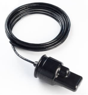
| Figure 1 - Base station Zima-B |
| Main view |
The base station is designed as a maintenance-free candy bar on a cable, embedded in a high-strength polyurethane compound. The station has a phased array antenna, a transmitting antenna, and an integrated depth/temperature sensor. As an additional option, the base station is equipped with a system for determining the course and position. In the general case, the base station is mounted on a rigid vertical rod taking into account the directivity of the antenna - the determined arrival angles are transmitted in the antenna coordinate system.
 |
|---|
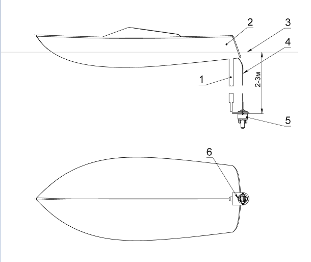
| Figure 2 - Zima-B Deployment scheme |
| 1-rod, 2-boat, 3-water surface, 4-cable, 5-Zima-B, 6-zero direction |
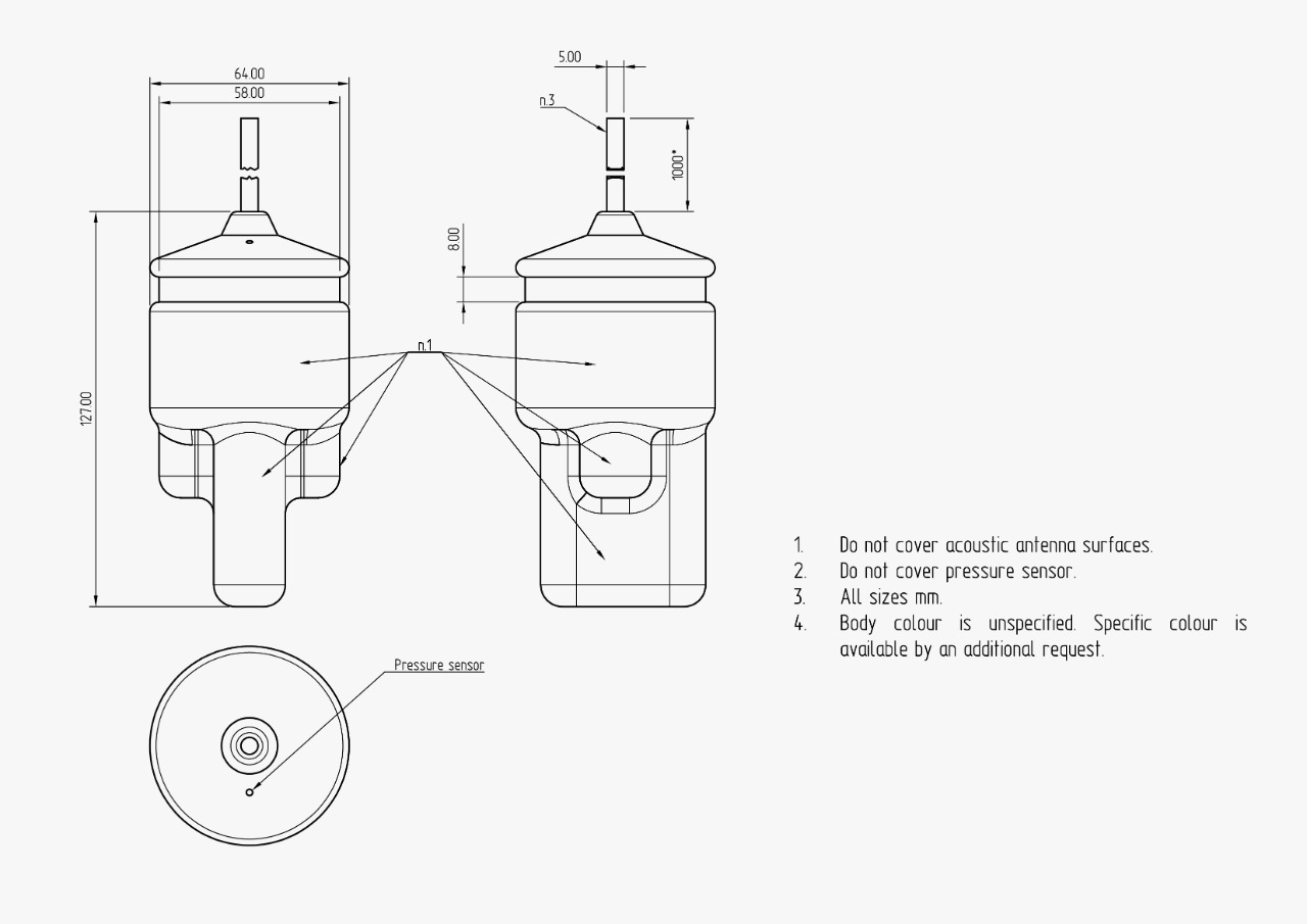
Figure 3 shows the outline drawing of the base station Zima-B. The base station has an input cable for energy and information pairing and an opening for the pressure/temperature sensor. Structurally, the base station is divided into the following parts: cable entry (in the upper part of the station) and a fixing groove for fixing the station with a clamp. Below is the cylindrical surface of the transmitting piezoelectric element, under which there is a receiving phased antenna array. The surface of the transmitting element and the receiving grille during installation should not be blocked or shielded. For proper operation of the station, line-of-sight is required between the working surfaces of the station and the antenna of the responder-beacon.
 |
|---|
| Figure 3 - Zima-B |
| Outine drawing |
In the standard configuration, Zima-B is supplied with a UART <-> RS-422 interface converter and cable 10 meters long, which is connected to the power supply and switching unit Bat & Link Box. Thus, through the switching unit, the station is connected to the control PC via the USB interface (serial port).
2.1.2. Technical specifications
| PARAMETER | VALUE |
|---|---|
| DIMENSIONS (Ф х h) | 64 х 128 mm |
| WEIGHT1 (dry) | 0.44 kg |
| DEPTH RATING | 300 m |
| MAX. OPERATING RANGE2 | 3000 m |
| ACOUSIC SOURCE LEVEL | 170 dB re 1 μPa @ 1 m |
| NOMINAL DEPTH ACCURACY | 0.1 m |
| HORIZONTAL ANGLE OF ARRIVAL ESTIMATION ACCURACY (typ.)3 | 1° |
| NOMINAL DISTANCE ESTIMATION ACCURACY | 0.3 m |
| MAX. TILT COMPENSATED BY THE BUILT-IN INCLINOMETER RELATED TO VERTICAL AXIS (pitch/roll) | +/- 30° |
| WORKING VERTICAL ANGLES (RELATIVE TO HORIZONTAL PLANE)3 | +/-30° |
| BANDWIDTH | 6 .. 18 kHz |
| BUILT-IN TEMPERATURE SENSOR ACCURACY | 0.1°С |
| BIT ERROR RATE | 10-6 |
| SNR3 | -3 dB |
| MAX. RELATIVE VELOCITY | +/- 2 m/s |
| RATED STARTUP TIME | 100 msec |
| WORKING TEMPERATURE RANGE | -5 .. 50 °C |
| BATTERY LIFE4 (WHEN SUPPLIED FROM BAT&LINK BOX) | 8 hours |
| INTERFACE | USB(COM) 9600 bit/s |
| PROTOCOL | NMEA 0183 PZMA |
| CABLE LENGTH5 | 10 m |
| SUBSCRIBER DIVISION SCHEME (commands/subscribers) | 32/23 |
1 Withoud cable and interface converter.
2 A parameter that determines the maximum range at which a signal can be received, based on electro-acoustic parameters of the transmitter and receiver, spatial decrease in the intensity of sound energy, attenuation in the medium and the acoustic noise level.
3 Obtained under laboratory conditions in a static test.
4 Considering 1 request in 3 seconds.
5 With additional cable and interface converter Bat&Link Box. Can be increased by a request up to 20 m.
2.1.3 Storage and maintenance
There are no special storage and maintenance requirements for the base station, with the exception of the following:
- When used in salt and/or heavily polluted water, desalination is necessary (flushing in freshwater)
- The use of any organic solvents, strong acids, alkalis and other aggressive substances is not allowed
- If necessary, washing in household soap solutions is possible, avoiding liquid getting on the connector
- Impact or significant static loads are not allowed.
- Strong (with a radius of less than 5 cm) cable bending is not allowed.
2.2. Zima-R: responder-beacon
2.2.1. General information
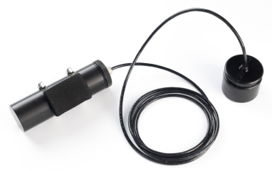
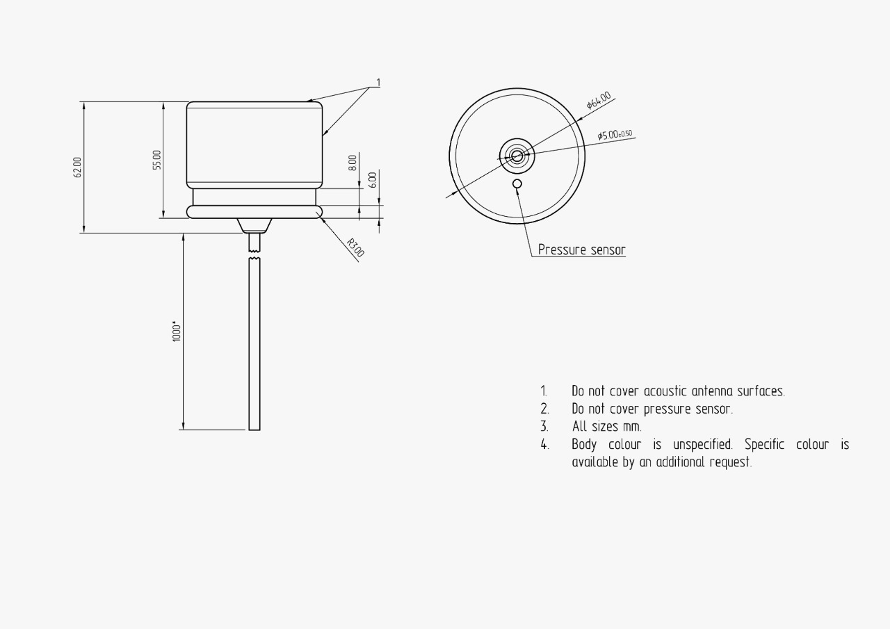
The responder-beacon is designed as a maintenance-free monoblock on a cable, embedded in a high-strength polyurethane compound. The appearance of the responder beacon [Zima-R] (Zima_R_Specification_en.md) is shown in Figure 4. Structurally, the beacon contains a cable entry, a mounting groove, a pressure sensor hole and a working surface. The pressure sensor opening and working surfaces (cylinder and cylinder end opposite the cable entry) must not be blocked or shielded. For correct operation of acoustic communication, line-of-sight between the base station and the responder-beacon is required.
 |
|---|
| Figure 4 - Zima-R |
| General view (autonomous version) |
2.2.2. Technical specifications
| PARAMETER | VALUE |
|---|---|
| DIMENSIONS (Ф х h) | 64 x 62 mm |
| WEIGHT1 (dry) | 0.3 kg |
| DEPTH RATING | 300 m |
| NOMINAL DEPTH ACCURACY | 0.1 m |
| MAX. OPERATING RANGE2 | 3000 m |
| ACOUSIC SOURCE LEVEL | 170 dB re 1 μPa @ 1 m |
| BANDWIDTH | 6 .. 18 kHz |
| BUILT-IN TEMPERATURE SENSOR ACCURACY | 0.1°С |
| BIT ERROR RATE | 10-6 |
| SNR3 | -3 dB |
| MAX. RELATIVE VELOCITY | +/- 2 m/s |
| RATED STARTUP TIME | 100 msec |
| SUPPLY VOLTAGE | 12 V |
| DATA LINES VOLTAGE | 0 .. 3.3 V |
| WORKING TEMPERATURE RANGE | -5 .. 50 °C |
| INTERFACE | USB(COM) 9600 bit/s |
| PROTOCOL | NMEA 0183 PZMA |
| CABLE LENGTH4 | 1 m |
| SUBSCRIBER DIVISION SCHEME (commands/subscribers) | 32/23 |
| HORIZONTAL ANGLE OF ARRIVAL ESTIMATION ACCURACY (typ.)3 | 1° |
| NOMINAL DISTANCE ESTIMATION ACCURACY3 | 0.3 m |
Additional parameters of standard battery pack5
| PARAMETER | VALUE |
|---|---|
| BUIT-IN BATTERY TYPE | Ni-MH |
| ELECTRICAL CAPACITY | 2.9 A*h |
| NOMINAL VOLTAGE | 12 V |
| NUMBER OF BATTERIES | 10 pcs. |
| CANISTER MATERIAL | Delrin |
| WORKING TEMPERATURE RANGE | -5 .. 50 °С |
1 Without a battery pack. Standard battery pack ф50х165 mm, 0.58 kg, 2.9 A*h 12 V. Operating time from a standard battery pack in standby mode - up to 70 hours, with radiation 1 time in 3 seconds up to 8 hours.
2 Without the presence of a multipath effect. A parameter that determines the maximum range at which a signal can be received, based on electro-acoustic parameters of the transmitter and receiver, spatial decrease in the intensity of sound energy, attenuation in the medium and the acoustic noise level.
Battery life with standard battery pack - up to 70 hours in receiving mode, up to 8 hours with 1 request in 3 seconds schedule.
3 Obtained under laboratory conditions in a static test.
4 Can be changed by a special request.
5 Standard delivery set, subject to change without notice
2.2.3. Configuration options
The responder-beacon Zima-R is a transceiver for underwater acoustic digital broadband communication and can be interfaced with the control system energetically and informationally. In this case, it is possible, if the control system has a magnetic compass, to determine the distance and heading angle to the base station, as well as receive telecontrol code commands from the base station. When autonomous, the beacon is equipped with a battery canister, as shown in Figure 4. In this case, it is completely autonomous and does not require pairing with the carrier underwater vessel. In OEM the beacon is delivered as a set of electronic boards for user installation in own normobaric housing. The responder-beacon is equipped with a deep-sea underwater acoustic antenna. Insertion of the antenna cable into the pressure-sensitive housing and switching with the beacon electronics, in this case, is provided by the user.
2.2.4. Work with the device (stand-alone version)
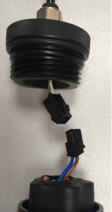
In this case, the responder-beacon is fully autonomous. For operation, it must be fixed on the carrier vessel in such a way that the working surfaces of the monoblock (cylindrical surface and end face) are not blocked by fasteners (a special groove must be used for fastening) and are not shielded by various structural elements of the carrier. To turn on the responder-beacon, the user needs to connect it to the battery pack using the connector, as shown in Figure 5.
 |
|---|
| Figure 5 - Connecting a responder-beacon to a battery pack |
In this version, the responder-beacon is equipped with a 10-cell nickel-metal hydride battery. The normobaric housing (canister) has a lid with a double seal and a four-thread, which allows the user to close the lid of the canister in 3/4 of a turn. Before immersion in water, make sure that the lid of the canister is tightly screwed (by hand). After connecting the responder-beacon connector to the battery pack within the first ten seconds, the device calibrates the atmospheric pressure, therefore it is not allowed to apply any (negative or positive) pressure to it during the first ten seconds from the moment the device is turned on, this will lead to incorrect depth measurement by the responder-beacon. With the autonomous version Tx and Rx, the wires of the beacon cable are closed (see Figure 6). This causes the UART module to automatically shut off in order to save energy.
 |
|---|
| Figure 6 - Zima-R |
| Outline drawing |
2.2.5. Work with the device (integrated version)
During energy and information pairing with the carrier vessel, the beacon transmits to the carrier the distance to the base station and the azimuth (only when the heading sensor is connected to the base station). In addition, in this case, the base station can transmit up to 28 code commands, about which the responder-beacon notifies the carrier in accordance with the pairing protocol.
2.2.6. Storage and maintenance
The responder-beacon does not require any special maintenance procedures, except for desalination and washing in running fresh water, after use in salt and/or contaminated water. In this case, the use of any lubricants or solvents, aggressive detergents, etc. are not allowed to remove contaminants from the responder-beacon and its cable.
In the case of using the responder-beacon in the stand-alone version, additional requirements are presented and measures are taken to service the battery pack and canister. In particular:
- long-term (more than one day) storage of the battery pack in the state connected to the beacon is not allowed;
- long-term storage of the battery pack without scheduled recharging (1 time per month) is not recommended;
- O-rings and the threads of the battery canister should be cleaned with water, a soft brush and a soap solution, followed by washing in running freshwater and greasing the o-rings with silicone grease;
- the canister is stored with the lid closed;
- when using the device in salt and/or contaminated water at the end of work, it is required to desalinate it in running fresh water.
3. ZHost software
3.1. System requirements
Specialized software ZHost (hereinafter referred to as the software) runs under the MS Windows operating system versions 7, 8 and 10. A monitor with a resolution of at least 1024x768 pixels and a mouse or touchpad are recommended. The software is portable, distributed as zip-archive (Download the latest version) and does not require any installation other than Unpacking to the user’s PC.
The executable file ZHost.exe, the settings file ZHost.settings and the required libraries are located in the root directory of the application. Localization resources are located in subdirectories corresponding to the localization language (e.g. \ru, \ru-RU, etc.).
When running, the application maintains log files. Logs are stored in the \LOG subdirectory, which contains subdirectories with the name of the current date (for example, \LOG\2020-01-21), which contain .log files with names corresponding to the file creation time (HH-MM-SS). A new log file is created each time the application starts. Log files have a text format and contain all the information exchange of the console software with the devices connected to it, as well as all errors that occur during the operation of the software.
When the AUTOSCRINSHOT function is enabled, the screenshots of the application window are saved in the \SNAPSHOTS directory, which also contains subdirectories by the name of the creation date, the window snapshot files are named by the current time (HH-MM-SS) and are in PNG format (Portable Network Graphics).
Since the connection with the base station is carried out by means of converters of the UART/RS-232/RS-422 interface to USB, additional drivers for a specific converter are required.
3.2. Description of the ZHost software interface
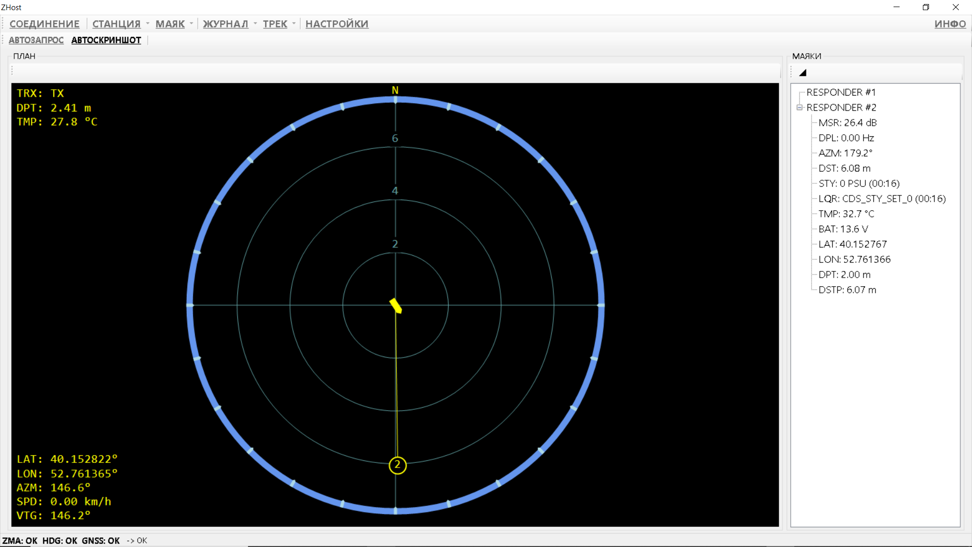
The general view of the application window is shown in Figure 7. It consists of a toolbar (menu) located at the top of the window, a status panel located at the bottom of the window; on the left is a screen for displaying the relative position of responder beacons (PLAN), and on the right is a tree structure containing the properties of the beacons used (BEACONS). The toolbar consists of the upper (CONNECTION, STATION, etc.) and lower (AUTO REQUEST, AUTOSCRINSHOT) subpanels.
 |
|---|
| Figure 7 - ZHost software |
| Main window view |
3.2.1 Toolbar
3.2.1.1. Menu item CONNECTION
The menu item “CONNECTION” serves to open and close the connection on the configured serial ports. These include the port, through which is exchanging information with the base station, AUX ports, through which navigation information from the GNSS + GNSS compass or GNSS + magnetic compass can be received (with appropriate settings), as well as a GNSS emulation port for one of the responder beacons.
When the user clicks on the menu item “CONNECTION” the application tries to open connections on the serial ports according to the settings. If additional providers of navigation data (GNSS, compass) are not specified and the system operates in relative coordinates, an attempt will be made to open the port for communication with the base station. If one or both of the AUX ports and the GNSS emulation output port are enabled in the settings, the software will try to open them as well.
If the ports are opened successfully, the menu item “CONNECTION” becomes highlighted, and subsequent clicking on it will close the connections.
3.2.1.2. Menu item STATION
The menu item “STATION” becomes active only after the connection with the base station is open and device information has been successfully received from it. The item contains the following subitems:
- “INFORMATION” to call up a dialogue box containing information about the connected base station (device serial number, firmware version, etc.).
- “DEPTH CALIBRATION” to call the dialogue box for setting the actual depth of the base station.
3.2.1.3. Menu item BEACON
This menu item becomes active only after the connection with the base station is opened and information about the device is successfully received from it, and the function “AUTO REQUEST” is not active. The item contains the following subitems:
- “SEND COMMAND” to call the remote command sending dialogue box, in which the user can select the address of the responder-beacon to which the user command should be sent and the command identifier.
- “CHANGE ADDRESS” to call the dialogue box for changing the address of the remote beacon-responder. In the dialogue box, the user must specify the current address of the beacon, which needs to change the address and the new address. The user should be careful when using this function. It is intended only for setting beacon addresses before submersion.
- “CALIBRATION OF ATMOSPHERIC PRESSURE” to call up the atmospheric pressure calibration dialogue box. In the dialogue box, the user must specify the address of the beacon. Upon receipt of a command to calibrate atmospheric pressure, the responder-beacon will use the current pressure readings from the built-in sensor as atmospheric. The user should be careful when using this function. It is intended only for configuring beacons before submersion.
3.2.1.4. Menu item LOG
Menu item “LOG” contains functions for working with application log files and contains the following sub-items:
- “VIEW”. Selecting this subitem will open the current application log file.
- “ANALYZE”. If the user selects this sub-item, the file selection dialogue for analysis will be displayed. The log file analysis function allows the user to quickly restore the system’s progress, for example, in order to restore the tracks of the vessel and/or responder-beacons in case of loss.
- “ANALYZE CURRENT”. The action of this sub-item is similar to the function of the “ANALYZE” sub-item, with the difference that the current one will be selected as the analyzed log file.
- “RESTART CURRENT”. When this sub-item is enabled, the contents of the current log file will be deleted and the log recording will continue.
- “DELETE ALL LOGS”. This menu sub-item is intended to delete all application logs from the LOG\ directory. Attention! Data from the log files will be lost forever!
3.2.1.5. Menu item TRACK
The menu item “TRACK” contains functions for working with tracks generated by the software and contains sub-items:
- “SAVE AS …“ serves to open a dialogue box for selecting a name and file format, for saving tracks. The function becomes active only if the system has unsaved geographic data. The software supports exporting tracks to Keyhole Markup Language (KML) and Comma-separated values (CSV) formats.
- “CLEAR”. This sub-item is used to delete all geographic data accumulated by the software for the current session. This function should be used with caution!
3.2.1.6. Menu item SETTINGS
The menu item “SETTINGS” is active only when the connection is closed and serves to call the dialogue box for changing software settings.
Settings are saved in the root directory of the application. It should be remembered that in order for the changed and saved settings to be used by the application, it must be restarted. If the settings are saved successfully, the software will display the corresponding prompt to the user.
The settings in the dialogue box are grouped for convenience, each group is located on a separate tab. RESET button is used to restore default settings. The OK button, which is used to accept the settings, is only active when the user has set consistent data (for example, with AUX ports enabled, the names for all the enabled ports must not coincide with each other).
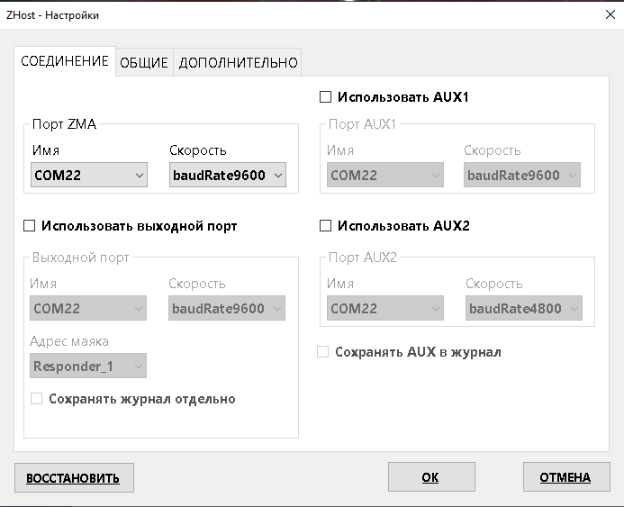
The CONNECTION tab contains the settings for the connection ports. Its appearance is shown in Figure 8.
 |
|---|
| Figure 8 - Settings editor |
| Tab “CONNECTION” |
The group “ZMA port” is always active and is responsible for the settings for connecting to the base station Zima-B. On commercially available devices, only 9600 bps is supported.
Other groups “AUX1 port”, “AUX2 port” and “Output port” become active only if the corresponding checkbox is selected.
-
If the system Zima USBL is used with a GNSS receiver with heading measurement function, then the user needs to use only one of the AUX ports through which data is received;
-
If the system Zima USBL is used with a standard GNSS receiver, and heading information is supplied from a magnetic compass, then both AUX ports should be used, a GNSS receiver is connected to one of them and a magnetic compass to the other.
If “Save AUX to Log” is not checked, then the data coming from the AUX ports will not be saved to the log file.
If the system operates in absolute coordinates (i.e., it receives data on the geographic location of the base station and its orientation relative to the cardinal points) and the absolute geographic coordinates of the responder beacons are calculated, then it becomes possible to emulate GNSS RMC and GGA messages based on the geographic location of the beacon and transmit them to the output port.
This can be, for example, a virtual COM port, to the second end of which cartographic software (for example, SAS.Planet) can be connected to display the location of the beacon on the map in real-time. To enable this function, it is necessary to check the Use Output Port checkbox and set the required port settings, as well as specify the beacon address, based on the coordinates of which GNSS data will be emulated.
If the checkbox “Save log separately” is checked, the data transferred to the output port will be saved in a separate log.
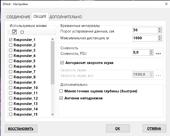
The tab “GENERAL” contains the address settings of the used beacons and some physical parameters. Its appearance is shown in Figure 9.
 |
|---|
| Figure 9 - Settings editor |
| Tab “GENERAL” |
The Used Beacons group contains a list of all possible beacon addresses. The system will automatically poll beacons, opposite the addresses of which are checked in this list.
The group “Time intervals” contains the settings:
- the threshold for data obsolescence (in seconds). If the value has not been updated more than the specified time interval, OBS (Obsolete) symbols will be displayed next to it in parentheses, indicating to the operator that this particular parameter (for example, water temperature or beacon supply voltage) has not been updated for a long time;
- The maximum distance. This parameter tells the system the maximum distance that the responder-beacon can be located. This parameter is responsible for how long the base station will wait for a beacon response. If for some reason the station does not receive a beacon response, it waits for it for a certain time, called a timeout time. It makes sense to set the minimum possible values based on the requirements of the task, in order to limit the downtime of the system when it expects a missed beacon response.
The Salinity group allows the user to set the salinity of the water (in PSU) either directly, or select from the world salinity database (by calling the salinity selection dialogue by the link ”..”). It is not recommended to take salinity from the base for small inland water bodies: rivers, lakes, ponds, etc. In this case, if the exact value is not known, set zero salinity (freshwater). The salinity value is used by the system to more accurately determine the depth and speed of sound.
The checkbox “Auto-calculation of the speed of sound” and the corresponding group managed by it are responsible for where the system will take the speed of sound in water. If this value is known directly from the measurement, the user should disable the automatic calculation function and specify the value directly. In other cases, the checkbox should be checked. In this case, the system will calculate the speed of sound by pressure, temperature and salinity. As a rule, the calculated value is in good agreement with the actual value.
Group “Advanced” contains:
- Checkbox “Less accurate depth estimate”. If this function is enabled, the beacon will transmit depth with a lower resolution (~ 40 cm), but at the same time, the depth will be transmitted in one request-response transaction, and the function of simultaneous navigation (sending back azimuth to the base station and measuring the distance by the beacon to the base station) will be unavailable. If the simultaneous navigation function is not required (for example, if a beacon is used in stand-alone version) and an accuracy of 40 cm in depth is sufficient, select this checkbox.
- The checkbox “Antenna is stationary” is designed for the situation when the system operates in relative coordinates and the base station is fixed motionless (for example, on a pier or other stationary facility of port infrastructure) so that its horizontal axis is directed to the north. In this mode, it is possible to transmit the reverse azimuth to the transponder beacons without the need for a GNSS receiver and compass.
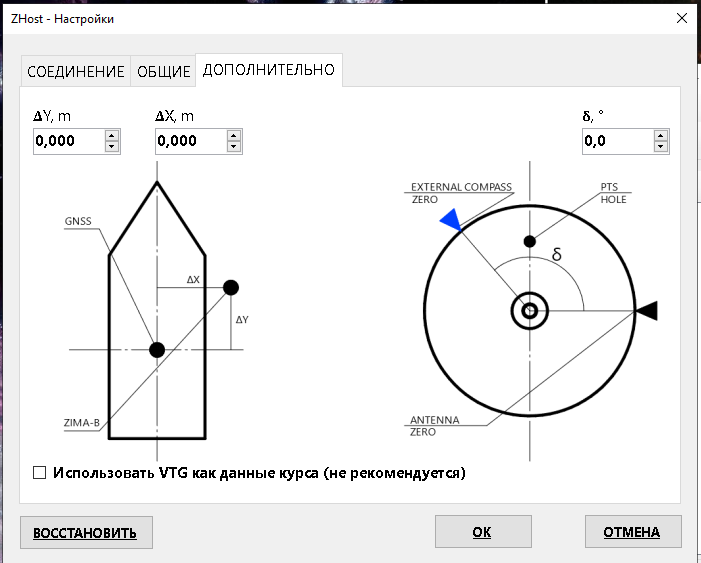
The tab “OPTIONAL” contains the settings for the orientation of the base station relative to the topographic position (GNSS antenna) and the zero direction of the compass. Its appearance is shown in Figure 10.
 |
|---|
| Figure 10 - Settings editor |
| Tab “ADVANCED” |
- Parameters “ΔX” and “ΔY” (in meters) determine the location of the base station in a rectangular coordinate system associated with the antenna of the GNSS receiver (according to the figure)
- The parameter “δ“ (in degrees) sets the zero rotation of the base station antenna relative to the zero of the magnetic or GNSS compass
3.2.1.7. Menu item AUTO REQUEST
This menu item controls the mode “AUTO REQUEST”. When this mode is turned on, the software will automatically interrogate responder-beacons at the highest possible speed according to the list “Used beacons” in “GENERAL” tab in the application settings window. AUTO REQUEST mode is the main operating mode of the system and should only be turned off if navigation data is not required or if a user command must be sent to one or more beacons (with AUTO REQUEST mode on, this function is not available)
3.2.1.8. Menu item AUTO SCREENSHOT
If this function is enabled, the software will automatically save the image of the main window when updating data. Files are located in the “\SNAPSHOTS\YYYY-DD-MM" directory, where “YYYY-DD-MM” is the current date. Each file is named according to the current time in the format “HH-MM-SS” and has the Portable Network Graphics (*.png) format.
3.2.2 PPI View panel
This panel (see Fig. 7) in the centre displays the position of the base station in the form of a yellow arrow, which is oriented from bottom to top when working in relative coordinates and changes its orientation when heading data is available. In the latter case, the symbol “N” (North) is displayed at the top of the limb. Panel “PPI View” displays the position of the beacons relative to the base station. Beacons are displayed as circles with the address of the beacon inside. When a timeout occurs (exceeding the waiting interval for the response of the beacon), the corresponding beacons are displayed with a dashed line.
In the upper left corner the current status of the base station is displayed:
- TRX: transceiver status (TX - transmitting, RX - waiting for a response, READY - ready for requests);
- DPT: depth (distance from the water surface) of the base station according to the readings of the built-in pressure sensor;
- TMP: water temperature according to the built-in temperature sensor.
In the lower-left corner additional data is received by the system via AUX ports:
- LAT, LON: geographical latitude and longitude (from RMC messages);
- AZM: azimuth angle (from HDG or HDT messages);
- SPD: speed (from VTG messages);
- VTG: heading (from VTG messages).
3.2.3 BEACONS panel
Displays data of responder-beacons in the form of a tree structure, where the nodes of the first level indicate beacons (“RESPONDER # ХХ”), each of which has a set of nodes indicating different parameters and characteristics of the beacons in the form of Parameter identifier: Value. Below is a list of possible parameter identifiers and their descriptions.
| Parameter identifier | Units | Description | Source |
|---|---|---|---|
| MSR | dB | Mean lobe-to-sidepeak ratio. Signal quality. 14 dB is the threshold, values above 20 dB a good signal quality | Determined by the base station when receiving a beacon response |
| DPL | Hz | Doppler shift | Determined by the base station when receiving a beacon response |
| AZM | ° | Aimuth from the base station to the beacon | Determined by the base station when receiving a beacon response |
| DST | m | Slant range from the base station to the beacon | Determined by the base station when receiving a beacon response |
| STY | PSU | Salinity value, that has been set to the beacon | From the response of the beacon, which confirms the setting of the parameter |
| LQR | - | Result of the last service request | Determined by the logic of the ZHost software |
| TMP | °C | Water temperature | From the response of the beacon, according to the built-in sensor of the beacon |
| BAT | V | Beacon supply voltage | From the response of the beacon as a result of direct measurement |
| LAT | ° | Latitude of the responder-beacon | Determined by the logic of the ZHost software |
| LON | ° | Longitude of the responder-beacon | Determined by the logic of the ZHost software |
| DPT | m | Depth (distance from the water surface) of the beacon | From the response of the beacon, according to the built-in sensor of the beacon |
| DSTP | m | Slant range projection on the water surface | Determined by the logic of the ZHost software |
The age of the data is displayed to the right of each value - the time that has passed since the moment the parameter value was updated. Age is displayed only if it exceeds 7 seconds.
3.2.3 Status bar
Located at the bottom of the window and displays the status of the relevant devices:
- ZMA: base station
- GNSS: geographical location
- HDG: azimuth data source
4. Effective use of the Zima USBL navigation system
The Zima USBL system is an underwater acoustic ultrashort base-line system that determines the relative location of responder-beacons by the propagation time of the acoustic signal in the water and the angle of arrival of the response signal of the responder-beacons. In this regard, its effective use is based on the following conditions:
- ensuring a stable position of the base station during operation; This condition is ensured by the reliable fixing of the base station on a vertical rod, taking into account the zero direction of the direction-finding antenna. Angular deviations of the vertical axis of the station from the vertical, as well as deviations and oscillations of its zero, negatively affect the accuracy of determining the angle of arrival of the response signal;
- ensuring direct visibility between the base station and the transponder beacon; Since the distance to the responder-beacon is determined by the propagation time of the hydroacoustic signal in the water, any obstacles in the signal path greatly distort the measured propagation time, and therefore the determined distance to responder-beacon; Obstacles can be attributed to both natural, associated with the bottom topography and/or coastal profile, as well as artificial ones - piers, mooring walls, ships with a deep draft, bridge supports and other technical structures;
- work surfaces should be free from various contaminants (silt, dirt, algae, etc.);
Due to the nature of the propagation of sound vibrations in the aquatic environment, the base station should not be located at a depth less than 2 - 3 meters and at least 1.5 meters from the bottom of the keel for small boats and not less than 2 - 3 meters for large boats.
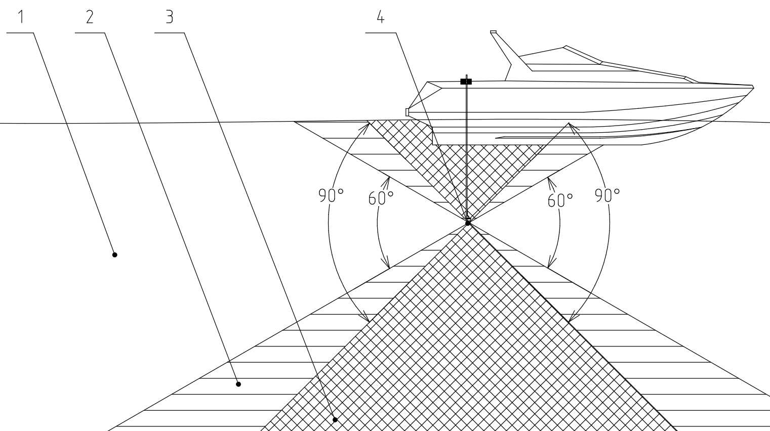
The antenna array of the base station is designed to determine the horizontal angle of arrival of the signal of the responder beacons, so it is worth remembering that with such a mutual arrangement of the antenna and the responder beacon when they are practically on the same vertical axis, the accuracy of determining the location of the transponder will be minimal. A good relative position of the antenna and the transponder beacon is considered to be such that the projection of the inclined range onto the water surface significantly exceeds its projection on the vertical axis. The working vertical angles of the base station Zima-B are angles +/- 30° from the horizontal plane passing through the antenna array of the base station. This provision is illustrated in Figure 11:
 |
|---|
| Figure 11 - Geometric limitations for Zima-B |
| 1 - work zone (+/- 30°), 2 - low accuracy zone (30 .. 45°), 3 - shadow zone ( > 45°), 4 - direction-finding antenna. The deviation is indicated from the horizontal plane passing through the center of the antenna array |
5. Possible malfunctions, their diagnosis and elimination
| № | Symptom | Possible reason | Elimination |
|---|---|---|---|
| 1 | Unable to establish a connection between ZHost and Zima-B (Error “COM port access denied”) | Feature of operation of drivers of the RS422-USB converter in Win8-10 systems | 1. Disconnect power to the Zima-B station 2. Disconnect the USB connector 3. Close the ZHost application 4. Connect the USB connector 5. Launch the ZHost application 6. Press the button CONNECTION at ZHost 7. Apply power to the Zima-B station |
| 2 | The station emits a request signal, but the beacon does not respond | Hydrologic conditions do not allow to provide sustainable communication | Check the serviceability of the responder-beacon at a short distance (0.5-10 meters) in line-of-sight conditions |
| The power connector on the beacon is not connected | Plug in connector | ||
| The battery pack of the beacon is discharged | Charge or replace the battery pack. | ||
| The requested beacon address does not match its actual address | In the ZHost settings, select all available addresses, the station will poll through all possible addresses one by one and thus the actual beacon address will be determined | ||
| The station may not have enough power and the signal may not be fully emitted | This is possible when the station is powered by power supplies that have a current limit. For normal operation in the transmission mode of the station, about 3A is necessary | ||
| 3 | There is no communication with the Zima-B station, the port is open, but the station does not transmit data | No power comes to the station | Check power supply and connection cables |
| Station defective | Replace station | ||
| 4 | Estimated angle of arrival has a static error | The zero directions of the station and the compass (or the longitudinal axis of the vessel) are located at an angle - the station is rotated in the clamp | Combine the zero direction of the station with the longitudinal axis of the vessel and/or the zero direction of the compass and prevent accidental rotation of the antenna in the clamp |
| 5 | The system works, the beacon responds but the absolute location of the beacon is not calculated (when an external GNSS receiver, compass or GNSS compass is connected) | Geographical position and heading are not updated | Verify that the GNSS receiver and the magnetic / GNSS compass as well as the connecting cables and port settings are working |
6. Liability and disclaimer
6.1 Terms of replacement and free warranty service
The manufacturer’s warranty applies only to factory defects that were discovered during the operation of the device in accordance with this manual during the warranty period (2 years from the date of purchase).
The manufacturer guarantees free repair or replacement of faulty equipment from the delivery set that has failed due to a factory defect.
The reasons for refusing free warranty service, free repair and replacement include:
- any mechanical damage of the equipment supplied, including violation of insulation of wires and cables;
- any damage caused by exposure to moisture and pollution due to improper use of the equipment from the delivery set: moisture in the connectors.
- any electrical damage caused by use of not original accessories;
- any signs of self-repair and/or opening of the equipment from the delivery set.
6.2 Disclaimer of the manufacturer
ANY OF THE PARTS OF THE DELIVERY SET SEPARATELY AND IN THE COMPOSITION OF THE SYSTEM:
- ARE NOT DESIGNED FOR RESCUE USE
- NOT TESTED AS RESCUE EQUIPMENT
- IS NOT RESCUE EQUIPMENT
- THE MANUFACTURER DECLARES THAT THE SUPPLIED EQUIPMENT IS SAFE WHEN USING ACCORDING TO THESE INSTRUCTIONS AND MANUFACTURER IS NOT RESPONSIBLE FOR ANY CONSEQUENCES OF USE OF THE SUPPLIED EQUIPMENT